Pinball info
You are using an out of date browser. It may not display this or other websites correctly.
You should upgrade or use an alternative browser.
You should upgrade or use an alternative browser.
Today I worked on......
- Thread starter kevlar
- Start date
 Beautiful work as always mate, it looks awesome! Just need you to do one for the main building now


I hope the "after" is the one with the hole......Today I worked on...
Made a start on making it easier to get Pins in and out the games room
View attachment 264441View attachment 264442

I hope the "after" is the one with the hole......


We should start a thread “look what I found in my coin box/behind my coin door”
All the stuff like new plastic kits, decals mods and more in the machine/coin box
BM66 - I have all the Hallmark figures for playfield, all the Topps cards for the apron.. so much random stuff in them.
BM66 - I have all the Hallmark figures for playfield, all the Topps cards for the apron.. so much random stuff in them.

I was asked fix this Funhouse scoop that has the usual broken spot welds. It’s now ready to go back in and should be good for another 30+ years now 


- Joined
- Aug 25, 2011
- Messages
- 126
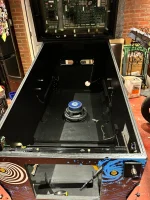
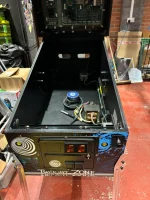
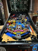
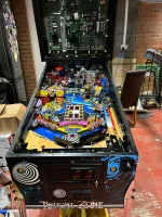
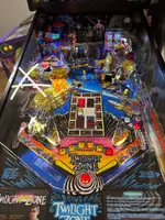
It’s been a busy time, but finally back on my TZ project.
The cabinet has be sanded, painted and new decals fitted and it’s now time to put the new repopulate playfield back in
Now for the wiring!
The cabinet has be sanded, painted and new decals fitted and it’s now time to put the new repopulate playfield back in
Now for the wiring!
Attachments
-
 80510545-719E-4CAB-8A07-FAFA119A8DF5.webp134.4 KB · Views: 26
 -
 14AB6BFD-A929-4222-B871-53B7576B947D.webp188.3 KB · Views: 23
 -
 C527F78D-072E-4C65-8F04-A19B9428552E.webp113.4 KB · Views: 22
 -
 E70FC3AF-9394-47FD-88A6-8E8249385C18.webp126 KB · Views: 22
 -
 EBB7FF4C-CAD1-440C-8607-726109B8A6E8.webp181 KB · Views: 21
 -
 E7B38CB6-5EE1-4884-8A5A-1B66357A66B5.webp197.9 KB · Views: 25
Last edited:
Today I decided to light up TWD Premium Bicycle Girl head that normal dwells in complete darkness.
1 warm white trough lighting kit, shrink tubing on half the lighting strip & the cable.
Wires feed neatly down where the ramp actuator comes up. Clip (or solder) onto GI lamp under playfield (white GI as Red dims during Bicycle girl mode)
Looks very neat, shrink sleeve hides the cable nicely.


1 warm white trough lighting kit, shrink tubing on half the lighting strip & the cable.
Wires feed neatly down where the ramp actuator comes up. Clip (or solder) onto GI lamp under playfield (white GI as Red dims during Bicycle girl mode)
Looks very neat, shrink sleeve hides the cable nicely.
Last edited:
Certainly makes a difference as didnt even know there was a head under there.

Fingers now sore after all that crimping, with sooo much more to do!! Made all the more difficult by the fact that (as far as i can see) there is Zero documentation on the cabling between boards on Sys11's. We were spoiled by the manuals on WPC and onwards as all the cabling was detailed in the manual... Sys11 it is a case of comparing cct diagrams of one board vs cct diagrams of the next... so much more time consuming!
(all the Red boards are Dumbass's boards - the two Green ones are originals).
Still waiting on topper nad currently dying with man flu but managed to do a little more on Elvira as armour turned up.
My new coater has done a cracking job!
Old standard black finish sandblasted off then sparkle powder coat with hard wearing lacquer on top.

Red washers and red rubber feet c/o Retro Dave and a set of my very own cab protectors.


My new coater has done a cracking job!
Old standard black finish sandblasted off then sparkle powder coat with hard wearing lacquer on top.
Red washers and red rubber feet c/o Retro Dave and a set of my very own cab protectors.


Visiting my dad for a couple of days and we spent the morning working on his Zaccaria Ten Stars (1976 EM). Playfield and plastics cleaned up and a new set of rubbers. Some mechanical gremlins to iron out and a bit of a flipper tune-up required but should be going up for sale at some point in the new year, any old Zacc fans keep eyes peeled!


Spent most of this afternoon giving Getaway a once over, comprising 3x brand new flipper mechs and sorted the cold solder joints on the traffic light

I was asked recently to make a couple of custom ball guides for a project. They needed to be cut down, welded and then re-grained to removed the weld/heat marks on the front.
First time I’ve seen or used the kit from Mantis but the parts and quality were spot on and I think its great that the kit is actually available especially if you pick up a project pin that’s missing a ball guide or 2.


First time I’ve seen or used the kit from Mantis but the parts and quality were spot on and I think its great that the kit is actually available especially if you pick up a project pin that’s missing a ball guide or 2.
- Joined
- Aug 25, 2011
- Messages
- 126
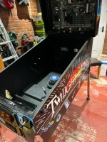
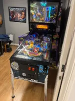
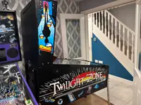
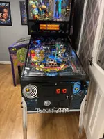
All done and space back in my garage, all the fine tuning done and one issue with it pumping the balls out the trough when a ball gotIt’s been a busy time, but finally back on my TZ project.
The cabinet has be sanded, painted and new decals fitted and it’s now time to put the new repopulate playfield back in
Now for the wiring!
Locked sorted, which was a wire off one of the optos at the top of the table, must have taken me 6 hours to find it.
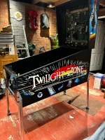
It look s and sounds stunning and plays beautifully, just waiting for a replacement trans light as all the paint Is falling of this one - it is 31Years old I guess.
Attachments
Today I worked on my Rollergames, which I picked up very cheap last month and so which comes with a bunch of associated issues to fix. I already replaced a few transistors, a couple of coils, several switches, rebuilt the flippers, and spent a looooong time trying to get the diagnostic coin door buttons going.
The remaining problems are twofold - firstly some electronics (hopefully just broken wires), and secondly aesthetic/practical.
A) The electronic: I’m trying to fix the situation where in coils menu nothing happens when testing ‘Flash 1’ (4 incandescent flashers) or ‘Flash 8’ (3 more under playfield flashers, presumably #89s or #906s). I’m stuck at the stage where I’m staring at this diagram and trying to work out where to look. Also the ‘insert board GI relay’, whatever the fuc_k that is.

I’ve tested the transistors, identified the wires and connectors where I can (what is “1P12-1”?) but am still struggling with these. Apparently I need to identify and diagnose any issues with pins on “5J5” and “2J4” even though the wire colours don’t seem to match those in the manual I may end up “shotgunning it”, ie reheating all the solder pads at connectors, and replacing all IDC wired connectors. Dunno if I can be ars_ed to do molex connectors tbh, as IDC works just fine in my limited experience.
B) the aesthetic: I’ve never done it before, but have decided to tackle the fact that loads of the inserts are raised up so it doesn’t feel flat, and the ball can be seen to jump.
Any tips on either of the above would be much appreciated. I know it’s a knackered old RG and have no intention of selling it or trying to profit off it, I just want to have a go at trying something new.

The remaining problems are twofold - firstly some electronics (hopefully just broken wires), and secondly aesthetic/practical.
A) The electronic: I’m trying to fix the situation where in coils menu nothing happens when testing ‘Flash 1’ (4 incandescent flashers) or ‘Flash 8’ (3 more under playfield flashers, presumably #89s or #906s). I’m stuck at the stage where I’m staring at this diagram and trying to work out where to look. Also the ‘insert board GI relay’, whatever the fuc_k that is.
I’ve tested the transistors, identified the wires and connectors where I can (what is “1P12-1”?) but am still struggling with these. Apparently I need to identify and diagnose any issues with pins on “5J5” and “2J4” even though the wire colours don’t seem to match those in the manual
I may end up “shotgunning it”, ie reheating all the solder pads at connectors, and replacing all IDC wired connectors. Dunno if I can be ars_ed to do molex connectors tbh, as IDC works just fine in my limited experience.B) the aesthetic: I’ve never done it before, but have decided to tackle the fact that loads of the inserts are raised up so it doesn’t feel flat, and the ball can be seen to jump.
Any tips on either of the above would be much appreciated. I know it’s a knackered old RG and have no intention of selling it or trying to profit off it, I just want to have a go at trying something new.
Last edited:
Mate I can’t help with the electronics but as for raised inserts.
You can heat them from beneath with a hair dryer to soften the glue. And either fully remove them, clean them up and re glue. Or soften the glue and tap the back down by placing a bit of wood over them tapping with a hammer. Or what I did, soften the glue, and put a piece of wood over it and (you’re gonna like this) get a deep throated G clamp and press it back down.
Ten years ago I found it impossible to find such a clamp in the the UK so bought one from abroad. You’re welcome to borrow it. I can post it to you.
There may be some pics of this in my old funhouse shop log from years ago. I’ll check….
Yeah here you go mate. You even comment on the clamp 

Complete Thread 'Funhouse'
Hey peeps
Not a proper one AT ALL. More like a wipe round with a rag but thought I'd document a couple of things as I go incase it helps anyone out with similar issues.
Picked this up on Tuesday night. Seller says its 100% working. As it's about an hour and half away I ask pertinent questions so as not to waste a journey. Sounds good so off I trot.
On arrival I'm quietly impressed with the general condition. I mean, this was a routed FH. I'm not expecting huge things. Cab looks good

Other side is faded but there's not a knock or mark on it, even the head is nice.
New...
Not a proper one AT ALL. More like a wipe round with a rag but thought I'd document a couple of things as I go incase it helps anyone out with similar issues.
Picked this up on Tuesday night. Seller says its 100% working. As it's about an hour and half away I ask pertinent questions so as not to waste a journey. Sounds good so off I trot.
On arrival I'm quietly impressed with the general condition. I mean, this was a routed FH. I'm not expecting huge things. Cab looks good
Other side is faded but there's not a knock or mark on it, even the head is nice.
New...
- Spandangler
- Replies: 25
- Forum: Shop Logs
Williams System 9 - 11 - PinWiki
I’ve tested the transistors, identified the wires and connectors where I can (what is “1P12-1”?) but am still struggling with these. Apparently I need to identify and diagnose any issues with pins on “5J5” and “2J4” even though the wire colours don’t seem to match those in the manual
1P12-1 means something like from PCB number 1 connector plug 12 pin 1. Typically a molex block.
5J5 means PCB 5 connector J5 (normally marked on the board).
2J4 means PCB 2 connector J4.
A) The electronic: I’m trying to fix the situation where in coils menu nothing happens when testing ‘Flash 1’ (4 incandescent flashers) or ‘Flash 8’ (3 more under playfield flashers, presumably #89s or #906s). I’m stuck at the stage where I’m staring at this diagram and trying to work out where to look. Also the ‘insert board GI relay’, whatever the fuc_k that is.
Dan,
If the solenoids associated with these two circuits (outhole and lock diverter) work, then the drive transistors are alright; the 'solenoid extender' or A/C relay is used to double up on the first eight solenoid drives. Flashbulb circuits have protective resistors, by the time Rollergames was built these were fitted to the Interconnect Board below the Cpu/driver board. When the A/C relay (on the Aux Power board lower right), is On, the 'C' load, usually flashbulbs, is connected to the solenoid transistor instead of the 'A' load, usually a solenoid. So the flashbulb drive circuit includes the Cpu, Interconnect and Aux Power boards. Hence the numbering system for boards and connectors, those three are boards 1, 2, and 5, probably in that order.
The Insert Board G.I. relay breaks the ac circuit for the general Illumination lamps on the Insert Board, behind the backglass/translite. It's most likely to be on the back of the wooden board itself. At first, a 'breaker relay' cut all the G.I., e.g. Blackout, but by this time games could have as many as three separate relays, though RG has two, for playfield and insert.
Incidentally, that picture of the solenoid chart shows yet another manual discrepancy; in the text above I see "Solenoids 23 to 27 c.... (connected via?) Sound Overlay Solenoid Board". That's left over from Whirlwind, which required even more drives.
Last edited:
Cheers Gaz, if that is your idea of ‘just a wipe with a rag’ rather than full shop job then I’d like to see what you do when you consider it a full 100% job. I like that guy’s Rudi dressed as KISS better than the original. I don’t own a hairdryer or a heat gun so will have to improvise, but yes please to a borrow of your long G clamp. I can’t be ars_ed to remove and reglue either so I’ll just heat and then hammer on a woodblock.Yeah here you go mate. You even comment on the clamp
Complete Thread 'Funhouse'
Hey peeps
Not a proper one AT ALL. More like a wipe round with a rag but thought I'd document a couple of things as I go incase it helps anyone out with similar issues.
Picked this up on Tuesday night. Seller says its 100% working. As it's about an hour and half away I ask pertinent questions so as not to waste a journey. Sounds good so off I trot.
On arrival I'm quietly impressed with the general condition. I mean, this was a routed FH. I'm not expecting huge things. Cab looks good
Other side is faded but there's not a knock or mark on it, even the head is nice.
New...
- Spandangler
- Replies: 25
- Forum: Shop Logs
Thanks Peter for the advice on first replacing all bulbs and I suppose I now have to dig in the harness looking for those molex blocks.
Jay, the backglass GI lighting is fine (it’s just the bulbs, right?) so I think I’ll ignore that. But I’m interested in what you say about the resistors on the interconnect board - those big sandy white block things? - so if the above doesn’t work, I guess I’ll be looking at those at some stage.
I’m starting to enjoy the diagnosis and repair side as much as the playing, which is just as well as I’m still completely shi_t at playing pinball, like Joey Deacon after several expressos


Last edited: