What's new
Pinball info

Register a free account today to become a member! Once signed in, you'll be able to participate on this site by adding your own topics and posts, as well as connect with other members through your own private inbox!

In Progress 1983 Bally GOLD BALL - Further Adventures in Budget Restoration

Well there's a question, @Jay Walker! But looking at the schematics in my lovely new GB manual I can tell you that the common one-to-sixteen decoder (74LS154) has been replaced with a one-to-eight decoder (74LS138) that feeds 7 momentary outputs controlled by PB0, PB1 and PB2 data lines from U11 on the MPU. The continuous outputs are controlled by lines PB4, PB5, PB6 and PB7, again from U11 on the MPU. PB3 isn't used by the solenoid controller, but is by the sound board.

The continuous solenoid assignments are:

PB4: OPEN GATE
PB5: COIN LOCKOUT
PB6: FLIPPER ENABLE RELAY
PB7: CLOSE GATE

So, you're right. No spare continuous circuits!
 
The continuous solenoid assignments are:

PB4: OPEN GATE
PB5: COIN LOCKOUT
PB6: FLIPPER ENABLE RELAY
PB7: CLOSE GATE

So, you're right. No spare continuous circuits!

I thought that might be the case, Peter. It has got a coin lockout, then? Losing that might've made a further saving, but Bally games usually released the lockout during a playfield reset, since a coin switch closing at that point would be ignored. In contrast, Stern had stopped using them by 1981 - neither Lightning or Freefall have one, even though they don't use all 19 solenoid drives.
 
Last edited:
I thought that might be the case, Peter. It has got a coin lockout, then? Losing that might've made a further saving, but Bally games usually released the lockout during a playfield reset, since a coin switch closing at that point would be ignored. In contrast, Stern had stopped using them by 1981 - neither Lightning or Freefall have one, even though they don't use all 19 solenoid drives.
I'm not even sure what the coin lockout is for? Is it to automatically reject coins or to prevent further credit being added during times when the game is not ready to play? I can there's a small solenoid that operates a horizontal bar that passes through all 3 coin mechs but I can't really see what it's doing inside.
 
The moving bar has wire loops attached (on a Stern game, anyway) which poke into openings on the coin acceptors, when the lockout coil isn't energised. These cause all coins to be rejected until the lockout is energised, withdrawing the loops. The lockout is energised once the game has completed its start-up test, and remains so until the game is turned off, put into test, slam tilted or the adjustable maximum number of credits is reached.
 
Wow! Thanks, @Jay Walker! You learn something new every day. I just had a fiddle with this on GOLD BALL (it's sat 2-foot behind me). Tried dropping a few coins in and most got stuck but the eject mech spat them out. Them I noticed one slot is marked "2 PLAYS 20 N.P." There's only been one size of 20p so low-and-behold I've just discovered that my GB is setup to accept modern 10p, 20p and 50p coins! The 10 and 50 slots are a bit iffy but the 20p works a dream. In the normal state the coin comes back out the front but if I push the lockout bar with my finger the coins then fall out the back of the mech!

AWESOME! :D
 
Did you notice the upgrade rom set for Goldball?
I've been working with Oliver Okaegi on a new attrackt mode, re-arranged the sounds a bit and some small changes in game rules.
You can find all on Oliver's website.
http://www.pinball4you.ch/okaegi/pro_soft.html

These are the rom changes:
Version date remark 12 280305
add 7-digit displays for player 1 - 4 (optional), add version nummber, recalculate checksum

installation notes (optional):
replace the four player 6-digit displays with 7-digit displays
Add an additional wire fom A4 (mpu) J1 Pin 7 to every player display pin 12 (don't connect the credit display!)

installation note:
burn the U6 amd U2 files on 2732 eproms.
after power on you will see the version number in the one player display.
You can leave the 6 digit displays in place no dip switch is needed, because goldball internally works with 7 digit scoring.

new with version 10:
improved attract modus (based on ideas from inkochnito).
enable freegame when dip 25 and dip 26 = on (credit not lower then 01).
This version is based on the bally gold ball service kit, this means when if dip14 = 0 and dip15 = 0 and dip16 = 0 the "gold ball" is reached when you complete the goldball letters.

Also dip24 = 1 means:
Top Rollover Button, Gold Ball special when flashing, comes on at the start of "Gold Ball" play, and every subsequent ball-in-play if not collected.
Also dip24 = 0 means: Top Rollover Button, Gold Ball special when flashing, comes on at the start of "Gold Ball" play.

For the following events the sound has been changed:
special award, 10 point rebound, Goldball complete, 30 points rebound, PLAY lanes miss letter center (left and right target), spot goldball letter, left return lane, top right star, right star, extra ball awarded, tilt, PLAY already lit, right and inner left outlane target 1, 2, 3 already lit, target 1, 2, 3,1-2-3 complete.
Play lanes (50k, extra ball, special) always reset if dip switch 7 is off.

new version 12:
corrected GI problem, goldball complete only played once.

Peter
www.inkochnito.nl
PS. If you need the rom file, just ask.
 
Did you notice the upgrade rom set for Goldball?
Thanks, Peter. I had spotted these as my VECTOR has the v5 ROMs from Oliver. My GB has custom ROMs but I've no idea what's on them as GB isn't working yet. They might even be just be the original code on EEPROMs.

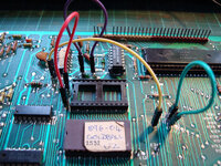
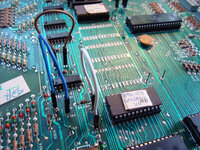
As you can see, I've customised the MPU board by adding header pins on all the "Ex" points so that I can quickly re-jumper the board for any ROM:

farm4.staticflickr.com_3837_15080092539_760e6ce527_c.jpg

farm6.staticflickr.com_5588_15266830215_9110817477_c.jpg

Rest assured though, once I get GB back up and running I'll be upgrading to Oliver's v12 software!
 
December 2014
Rebuilding the AS-2518-147 HV LAMP SOLENOID COMBO Board

My wife announces she's going sales shopping with her sister this morning (Sunday 28th), she'll only be a few hours, etc., etc. Needless to say she didn't get home till gone 6pm but it meant that as well as having a fun day with the kids playing computer games (FEZ) whilst making the odd bit of food I could slip off unhindered to my man cave ;)

This time I decided to attack the 190VDC regulator for the displays (and I've just noticed in this photo that Q18 has a hacked leg - will replace that eventually):

farm8.staticflickr.com_7542_15948901808_7d2463a06d_c.jpg

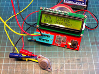
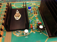
Typical cascade failure, all the transistors and several resistors fried. I couldn't find any 140V zener diodes so I went for 130V, which I thought would be fine as I want to run the displays at a slightly lower 160V to extend their lifetime instead of the factory 190V. I also couldn't find a 25kOhm trimmer with the same pin spacing a but managed to get a 20k trimmer which fitted after some judicious leg bending. My guess is the lower value will just slightly reduce adjustment range:

farm9.staticflickr.com_8582_15514015134_65de3b8ee9_c.jpg

Somehow I've misplaced the five BUX84 transistors I bought to replace the 2N3584 (Q33) but found one original on a spare faulty regulator board from my Big Box Of Bally Boards tested just fine:

farm9.staticflickr.com_8629_16110559006_bf9588bd0b_c.jpg

All done, apart from R56. CPC Farnell sent me 270R 1/4W instead of 390R 1/2W resistors, so I refitted the original as it tested ok. Will fit new when replacements arrive from CPC. All components have been mounted slightly proud of the board surface to help with cooling (you can see the board was burned brown under R54 when it failed):

farm8.staticflickr.com_7486_15516614653_1af8b27084_c.jpg

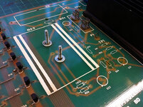
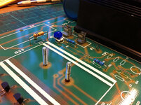
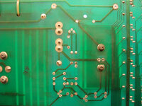
I also made sure the electrical connection on the mounting bolts of Q33 (2N3584) were sound because on the AS-2518-147 board they provide a connection between tracks on the underside of the board (the TO-66 case of Q33 is the collector). I think this is why the heads of the bolts are soldered onto the board:

farm4.staticflickr.com_3920_15400522595_ef480f9005_c.jpg

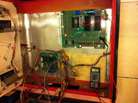
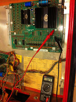
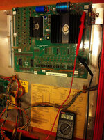
Also fitted a new Philips 150uF 400V electrolytic capacitor at C5. Should be 160uF but most likely way better than what was there and close enough. Time for testing! Mounted it in the backbox and only connected J7 (top right) to provide the +190VDC, +13-16VDC and GND. After a quick adjustment of the trimmer I have a steady +160VDC at TP2:

farm9.staticflickr.com_8609_16110557466_dbcafbcb3e_c.jpg

A quick check that the +5VDC section is still doing it's job and we've got +5.23VDC at TP5:

farm8.staticflickr.com_7527_16135593092_3e200e9a2a_c.jpg

And another quick check on the input to the +5VDC regulator which should be between +13-16VDC, and we've got +15.78VDC at TP4. Nice!

farm9.staticflickr.com_8591_16134444231_ffa4210dd5_c.jpg
 
December 2014
FIRST POWER ON!!!

So, the regulator board is all fixed :D Just need a working MPU now... ;)

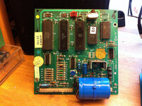
If you've been following this shop log you'll know that I fixed the MPU but for some, as yet, unexplained reason it stopped working again. But I've also managed to fix one of the -35 MPUs from my Big Box of Bally Boards, so I did the same mod of putting header pins on the "E" points so it can be easily re-jumpered for any ROM combination:


In the case of GOLD BALL, I have a 2532 EEPROM for U2 and a 2732 for U6. I put the MPU in the backbox alongside the newly fixed HV LAMP SOLENOID COMBO and connected just J4 as this supplies the +5VDC and 11.9VDC.

Interestingly, the +43VDC for solenoids is not used to power the ZERO CROSSING DETECTOR circuit on the MPU, but instead the ∅A-channel Switched Illumination is used to supply Pin 15 on J4. The 2k resistor R112 on the MPU is replaced by CR52, a 1N4148 diode, presumably because the Switched Illumination is AC and this provides simple half wave rectification. The schematic also has the value 21.5VDC for TP3 crossed out because ∅A supplies around +10 VAC.

Anyway... switch on! And we're off to a good start as the MPU does it's full 7 flashes, indicating the ZCD circuit is happy and U10 and U14 are working too.

So, I decide to throw caution to the wind and plug everything else back in. This is what happened:


Oh dear... :( Looks like I've still got my work cut out! So, I've got some sounds (nice), a few brief flickers on the displays, some GI and a few inserts, and some relay/solenoid clicks. Strangely it's different every time the machine is switched on: the MPU seems to reset/reboot occasionally and even weirder the centre pop bumper goes totally mental non-stop.

At this point I'm suspecting some iffy ground connections because (a) I haven't done the ground mods on either the MPU or COMBO board, and (b) I was really lazy and didn't screw the boards onto their mounting brackets.

After I've made those changes I'll pull all the connectors and do a power-up after adding one connector at a time.
 
New Years Eve 2014
MPU FIXED!


Finally fixed the MPU. After much chip swapping, re-soldering and even analysing with an oscilloscope it turned out to be a duff U9 6800 CPU. It was fitted with an AMI S6800P from KOREA but as soon as I popped in an authentic Motorola MC6800P the repeated rebooting stopped! So, now I have a working MPU and HV REGULATOR. This is what I get after power on. It goes into attract. The 15 is after I added some credits using Chute #3, so that display is in the wrong position. But the Start button doesn't do anything. The coin door test switch is broken but touching the wires does put the MPU into test mode. A lot of lights are out, the sound has gone a bit wonky and half the solenoids aren't popping. Apart from one digit the displays are all good. Very happy so far!

I'm off out to a party now, so HAPPY NEW YEAR EVERYONE!!!

:D
 
January 2015
BITS 'N' BOBS

Managed to grab a hour today. Soldered on a push-to-make switch for the coin-door diagnostic button. It's too big but it works. Have some new buttons coming from eBay soon.

Also, found out why the single slingshot coil was disconnected... it's stuck on! Someone must have pull off the wire as it wasn't cut. As soon as I switched the machine on I heard a coil go "THWACK" a knew what had happened. Hastily switched machine off and cut cable off again. Will need to trace the fault ASAP on that one!

I also worked out the colour of the controlling wires (Pin 15) to get the displays hooked up in the correct places. Display 1 has an iffy 4th digit that flickers a bit, maybe a dodgy latch or transistor? And display 4s fourth digit is totally out. Suspect dead driver chip/transistor as it was like that before I got the connectors in the right places.

Another thing that crossed my kind was that the S1-32 switches on the MPU would be all over the place as the board came from a totally different game, so checked the manual and set them back to the recommended defaults for a 3-ball game.

But in better news I did get one of the flippers to work! I realised that the start button would probably only work if it thought there was a ball in the tray (there aren't any balls in the game at all as it's still such a dirty mess). So I held the tray switch with one hand and pressed the start button with the other and got a game to start! Right flipper works great but nothing from the left. Another dead SCR? Haven't ever had to fix a coil circuit before...
 
Have a look at this webpage for fixing Bally displays:

http://stevekulpa.net/pinball/bally_disp6r.htm

I've used the info to fix displays in both my Flash Gordon and Fathom and it's sorted the issues every time. Replacing the relevant resistors and both level shifter and digit driver transistors for each display generally gets everything working 100% :)
 
Right flipper works great but nothing from the left. Another dead SCR? Haven't ever had to fix a coil circuit before...

I doubt it. Try cleaning all switching contacts first - eg flipper button and EOS. Then check continuity over each switch and then the wires themselves to and from the flipper buttons to the coil.
 
On a 'conventional' (pre-Fliptronic) game, the current circuit for a flipper coil is basically as follows;

  • 'live' supply to coil
  • Primary winding
  • End-of-stroke switch (by-passing secondary winding on serial-wound coils)
  • Flipper button contacts
  • Relay contacts (closed with relay energised)
  • Ground
Like any other coil, a flipper coil can be momentarily energised by connecting a jumper wire between the 'tail' end of the winding(s) and ground, by-passing the regular wiring.

On GoldBall, the flippers aren't likely to have seperate fuses for left and right, so this one's probably a case of burnt contacts - e.g. the combined resistance of the primary & secondary windings is too great for the flipper to even move if the EoS switch isn't making good contact.

As for the slingshot coil, that's got a continual path to ground. The most likely cause is a damaged darlington transistor (TIP 120/SE 9302), though the relevant transistor array (CA 3081) chip could also be at fault.
 
Last edited:
Thanks @ronsplooter, @Moonraker and @Jay Walker! I spent a few hours inbetween "lunch" and "work" fiddling, testing, poking and standing back whilst muttering "Mmmm...."

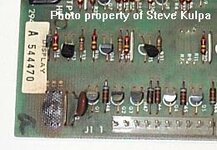
The display was an easy fix. Didn't need to test it to see that resistors R1, R3, and R5 have been running a little "hot" just like Steve Kulpa's photo:

stevekulpa.net_pinball_b_disp_b1.jpg

Turns out R5 (left most resistor) was dead hence why the 100s digit was out. R1 and R3 just about ok but reading a little low at around 75-80k. I replaced R5 with a 1/4W 120k as that's all I have to hand and it's working again. My next order with CPC will include 50 x 1/2W 100k resistors! Display #1 still has a slight flicker around the fourth digit so suspect similar there too, or maybe a flaky transistor or dry joint.

The transistor Q42 for the slingshot coil was also toast (GOLD BALL only has 1 slingshot - the other slingshot is "passive"). Replaced the original 2N6045 with a TIP102 and popped in a new 1N4007 diode for good measure. I haven't tested it yet as I'm not 100% sure about the coil. It moves freely, reads about 10 ohms and all the wiring is sound, but it has no identifying label and the wrapper is very brown. As I can't identify it with certainty I don't want to hook it up and fry the TIP102. Annoyingly the manual omits to state which coil the slingshot takes, but as it's one of the newer "linear" flippers like my VECTOR I'm going to order and fit a new AO-26-1200.

And finally the left flipper... I checked all the wiring, the complete circuit from power supply to button to solenoid board to coil and back to the power supply. I even took the case off the relay and checked and cleaned the contacts. All good. Checked the coil itself and one side is totally open circuit! That's when I spotted it's also the wrong coil. Should be an AQ-25-500/34-4500 but someone's fitted an A-24-570/34-3600! And when I say "fitted" I mean botched with some terminal block and the ****tiest soldering you've ever seen. I'll be ordering a new flipper coil too ;)

The thing that's bugging me the most though is the sound. It's makes a sound whenever a switch is pressed but it's the same sound for everything. Only time it plays anything different is pressing the outhole switch. There's no background sound either. I've set Self-Test option #18 to all four values (00, 01, 02 and 03) but it's always the same. I gave the sounds board a bit of going over - removed all the chips and cleaned the pins, checked the values of the larger electrolytic capacitors, cleaned the header pins, reflowed soldered and even put in a new 6821 PIA - but to no avail. I only know roughly what to expect from Todd Tuckey's video:

 
Last edited:
Found a very interesting video on YouTube about using an Arduino as a source of test signals for triggering the AS-2518-51 sound card:


Looks like I have a project for my new Arduino MEGA ;)
 
So after a bit more "prodding" the A8 SOUND MODULE has complete given up. Not a squeak.

I've tested two of the chips, the 6821 PIA and 6810 SRAM, as they are also used in the A4 MPU MODULE. Of the big chips that leaves the AY-3-8910 PSG (Programmable Sound Generator), the MC6808 CPU and the U4 ROM containing the unique GOLD BALL sound code. I've no way of testing the CPU (the MPU uses an MC6800) or ROM, but I have ten MC6802 CPUs on their way from China (these have built in RAM unlike the MC6808 so can ditch the external 6810 SRAM) and superbly helpful Jim aka @myPinballs is doing me a fresh U4. So that leaves the PSG...

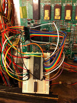
Well, I've been looking for something to do with my new Arduino MEGA. There's plenty of info on the 'net and eventually I got this simple rig setup using a 74HC595 for latching the data lines. The 8 red LEDs show the data lines and the 3 green LEDs show the control registers. There's a 100ms delay between every step otherwise everything flashes so fat you can see anything!


Next it was a simple case of replacing the LEDs with the actual AY-3-8910. This chip requires a 2MHz clock signal but I don't have crystal oscillator to hand so divided the internal 16MHz Arduino clock signal and pushed it out of one of the ports.

I realise this isn't the most stunningly music demonstration but it shows it works:


Unfortunately it does look as though the AY-3-8910 is faulty because after about 30 seconds the sound gets distorted and starts to fade away. The longer the circuit has been on the less reliable it is the next time it's rebooted.

Looking forward to getting those ten AY-3-8910s I ordered from AliExpress.com, the consumer version of Alibaba :D
 
January 2015
SOUND MODULE PROGRESS

I haven't managed to bring it back to life but I am making some progress with the sound module. You can see in my previous post I got the AY-3-8910 working using an Arduino microcontroller. But it's not a happy chip. After a minute or so the sound starts to deteriorate.

farm8.staticflickr.com_7493_16239444606_efba5e94ba_c.jpg

To test my test rig (!) I pulled the similar AY-3-8912 chip from my VECTOR. It's a 28-pin chip but has the same gubbins inside as the bigger 40-pin AY-3-8910 from GOLD BALL, except it only has one set of 8-bit I/O ports. As the Arduino test rig doesn't even use the 8-bit I/O ports it was a simple case of moving a few of the jumper wires around on the breadboard. Guess what? Works perfectly. Keeps playing the same test tune over and over again, and in much better tuning as well.

As a final test of the AY-3-8910 I patched it into VECTOR using breadboard and jumpers:

farm8.staticflickr.com_7469_16077991990_6fb30f0c6a_c.jpg

No surprise really that the test LED didn't complete all it's flashes, stopping after just three. No fourth flash means U12, the AY-3-8910 is faulty.

I then attempted to patch the 28-pin AY-3-8912 into GOLD BALL, but alas, still no sound. I also switched over the MC6808 CPUs. The one from GOLD BALL is definitely faulty as the LED on the VECTOR SQUAWK & TALK just stays lit. But the good one from VECTOR doesn't get the GOLD BALL sound module working, so there's still something else wrong. I know the 6821 PIA and 6810 SRAM are good, so maybe the U4 ROM is bad and/or other chips/components on the digital side of the board?
 
January 2015
FIXING THE DEAD LEFT FLIPPER
I'm putting the sound module to one side for now as I'm waiting for new chips to arrive. After bringing the game back to life by fixing the PSU, MPU and REGULATOR modules it's time to start getting a playable game going. First issue holding up proceedings is a dead left flipper.

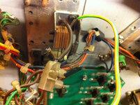
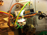
First inspection revealed some ropey wiring held together with terminal block and burnt wires with exposed cores. They'll have to be replaced eventually. The coil itself was open circuit but it was also the wrong one: an AQ-24-570/34-3600 when it should be an AQ-25-2500/34-4500, which I ordered from @pinballmania. At least I've now got plenty of spare enamelled wire for those custom LED mods that @Hiro996 keeps doing ;)

farm8.staticflickr.com_7498_16280391981_4f507e8cb2_c.jpg

Not the most elegant repair but it'll do for now so that I can at least get it working to see if there's a fault anywhere else. Going to have to replace those blue (lamp) and orange (right flipper) wires as the cores have been exposed! The yellow-green wire should be grey:

farm9.staticflickr.com_8660_16096312937_ea3560c3d5_c.jpg

In time I'll service the entire flipper mechanism but for now I just polished the plunger (note Bally "Linear" style) so that it doesn't wear the brand new coil sleeve.

After fitting the new coil does it work? Nope. Bugger. Ok, back to basics. Unplug the mains and pull the A3 SOLENOID REGULATOR module. Bally SS flipper circuits are really simple. They just take +43VDC from the PSU at A2J1-7 to the coils, then on to the SOLENOID module, A3J5-13 (left) and A3J5-14 (right). The only reason this is done is because this is where Bally have located the FLIPPER ENABLE RELAY (controlled by Q44). From the relay the circuit leaves the board via A3J6-1 (left) and A3J6-2 (right) back to the flipper buttons and then back to the PSU at A2J2-2.

NOTE 1: GOLD BALL has the unusual AS-2518-147 A3 LAMP SOLENOID REGULATOR COMBO module that was only used in GOLD BALL and GRAND SLAM. It's similar to the combo board used in Baby Pac-Mac and Granny and the Gators.
NOTE 2: The connector information in the PLAYFIELD wiring schematic of the Bally GOLD BALL manual is wrong. It states wire from flipper coils go to A3J6-1 and A3J6-2, but these are the return pins back to the flipper buttons!


I tested everything for continuity and it all checked out. Even the relay. Mmm... what else? I checked the resistance across the coils (flippers are double coils). Putting the meter across the outer lugs of the working right flipper I got a reading of 3.5 Ohms. Nice. Low resistance, high power kick. Press in the plunger to open the EOS switch and in kicks the high resistance holding coil and I get around 240 Ohms. Also nice. So then I try on the new coil. Uh-oh! 250 Ohms across the outer lugs straight away. That can only mean one thing - a totally open-circuit, non-conductive EOS switch. Oh my God! You have never seen so much carbon scorching in your life! I had to chip it off before getting to it with the wet'n'dry. But eventually I found some bare metal and a closed resistance of 0.4 Ohms. Popped it back in the circuit and Hey! Presto! working flipper.

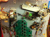
All done under here for now. So sparsely populated compared to VECTOR or PARAGON. By 1983 Bally really were trying to minimise costs in the battle against video games:

farm9.staticflickr.com_8669_15662307103_39524c414e_c.jpg

I FINALLY GET TO PLAY MY FIRST FULL GAME OF GOLD BALL :D IT'S BACK! ANOTHER PIN SAVED!

Peter you are doing sterling work (to say the least) on the Gold Ball and I'm really enjoying your shop log! Though I do feel guilty when you list all the things wrong / broken. It *was* cheap mind ;)

Also if I still had it it would still be sitting there in 10 years time! Then when I finally plugged it in I'd probably give up on it when it got too difficult...... :rolleyes:

Looking forward to the vid of it up and running!

Looks as though I'll finally have to put that video up on YouTube for @andy :D

Also, whilst I had the soldering iron out on the machine I fitted a new Self-Test button on the coin door:

farm9.staticflickr.com_8573_16282178565_557c5e8a30_c.jpg
 
January 2015
PLASTICS

Now that I have a playable game it's time to start fixing, cleaning and restoring the playfield. It's disgustingly grotty and now that I've had a couple of plays I must resist the temptation as all it's going to do is grind more dirt into the playfield and cause more wear.

First thing to come off are the plastics. I've been really luck again with my second project pin in that the plastics are complete and appear to be in pretty good shape. Very grubby but nothing that a little Novus #1 and #2 can't fix. The only damaged plastic is the top-right apron arch - the corner has been snapped off, probably by someone too lazy to remove all the screws - but luckily it's unnoticeable as it is mostly hidden under the chrome bar that holds the glass.

Sample grot:

farm8.staticflickr.com_7481_16256371626_77c481665c_c.jpg

farm8.staticflickr.com_7557_16256370566_b0d3a7cab3_c.jpg

farm8.staticflickr.com_7555_16280513621_d02aa5ddf4_c.jpg

But everything cleaned up really nicely:

farm8.staticflickr.com_7564_16281467642_af20dae216_c.jpg

farm8.staticflickr.com_7512_15662432513_2d751af35b_c.jpg

farm8.staticflickr.com_7488_15662432163_78e830e3ba_c.jpg

One complete set of shiny plastics (notice broken corner on top-right apron arch):

farm8.staticflickr.com_7468_16096167219_b81c06eb8b_c.jpg

Quickly popped them back on the playfield to see how they looked. Much better already!

farm9.staticflickr.com_8572_16281459302_942664abf2_b.jpg
 
Did you use power tools to buff the plastics, or is it all elbow grease pls ?
 
Did you use power tools to buff the plastics, or is it all elbow grease pls ?
Pure elbow grease on the plastics using Novus #1 first to gently clean off the dirt (no rubbing as it scratches) then #2 to cut through the tougher grime and light scratches, and occasionally some #3 to deal with heavier scratches. All done using separate Novus Wipes whilst on a 3-hour conference call at work!
 
  • Like
Reactions: JT.
You sir, are a machine...

Very impressive work. Keep it up and keep posting your progress, you might embarass me into doing something with some of mine (havent even set the machines back on their feet since they returned from the league meet in November)

Cheers
Ian
 
Dude do you ever sleep !?!?
Such is the joy of being an insomniac :confused:

You sir, are a machine...
A few slow machine, but thank you! I realised yesterday that I'll have had PARAGON for 2 years this March. Not exactly what you call rapid progress. In the same my mate @Hiro996 has managed to shop and mod at least 6 pins, but then I suppose he doesn't start with non-working rusty junkers from the 70s like me ;)
 
As promised for @andy it's VIDEO TIME!


I added some cheesy dance music because the sound module isn't working and you'd have to listen to rolling ball sound and me sniffing! The track is called "Pinball (Original Mix)" by Spacebeat. First game was terrible! Straight down the middle. But the second game was much better. Good pop bumper action around 2:15. I LOVE POP BUMPERS :D VECTOR is a bit of a disappointment in that area. And it's got the skill thing on the right flipper that cycles the lit lamps on the lanes at the top. I like that a lot too. It's got my other fave retro gizmo: a spinner. And a reversed outlane on the left. It could do with a saucer or two - I like those - but doesn't feel unusual for not having any drop-targets.

Overall it's a very simple game but even though the playfield is crusty as hell and it's got snapped/perished rubbers it plays pretty fast. Sometimes the ball whizzes around. I can't wait to get some clearcoat on it.

For a random purchase GOLD BALL is really growing on me already...

And yes, I am feeding a 20p coin into it to register credits!
 
I also replaced/fixed all the dead lamps this lunch time. The "3" and "6" THOUSAND inserts aren't working (and watching this video it looks like "9" has gone again) so I suspect a couple of dead driver transistors on the LAMP COMBO board, but everything else is good. Not sure about the white 50,000 insert right at the top as it appears to be on all the time?

I tested all the switches too and they're all working, none stuck. The only solenoid that isn't working now is the KNOCKER (05). Coil tests ok so, again, probably a bad transistor. The OUTHOLE KICKER is a bit weak. You can see in the video I need to give it a helping hand occasionally hence why the apron has been removed.
 
Back
Top Bottom