What's new
Pinball info

Register a free account today to become a member! Once signed in, you'll be able to participate on this site by adding your own topics and posts, as well as connect with other members through your own private inbox!

In Progress Rocky & Bullwinkle Shop Log

Ok just read the other thread on this and I'm thinking in BW terms rather than DE which it looks like they're using transistors to run the switch matrix rather than one enclosed in a IC like modern BW do... :rolleyes: So yes you need to replace Q51 if I've correctly understood the other thread.
Phew!!

Apologies for that - I had no idea that DE and BW tables handled things in a slightly different way.

I've just got back from Maplins with two 2N3904 transistors and my cable label tags have also turned up. So i'm going to make up some labels later and get the cables all labelled up before stripping out the CPU board for repair.

Thanks for the help guys - i'll be sure to report back.
 
Well if they're still not working after replacing the transistor... that would then leave you with needing to replace the LS244. :confused:
 
Hurrah!! Good news!! I've replaced Q51 and now all switches on that column work.

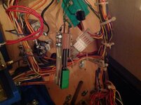
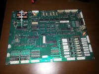
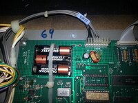
Stripped the CPU board from the machine. Here it is - isn't she gorgeous!!!

20130905_175322.jpg

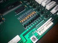
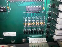
And there's the naughty Q51 which has been nicely baked.

20130905_175328.jpg

The old transistor was a little stuborn coming out - I desoldered from below but a couple of the legs were clinging on with solder on the top of the pad and I really didn't want to pull and risk lifting a track or damaging anything. In the end I lifted one leg clear and clipped the other too with some snips. Then carefully applied heat whilst pulling the legs free.

20130905_182855.jpg
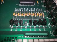
Then it was just a case of pulling the legs of the new transistor into place and cutting them to length before bending them accordingly. A few minutes later and they were soldered in place. I didn't get a picture of the bottom before it went back in the cab but it was pretty tidy. Unfortunately the top side looks a little dark, almost like it was burnt but I have no clue why as I was very very liberal with the iron. Not to worry. There was a good strong contact on all three legs.

20130905_185637.jpg

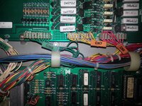
Before stripping the CPU board out I took a few moments to make up some labels and tagged the cables too. I'm going to do this throughout just for my own sanity. When the machine arrived I had to strip the head entirely and reassembling it was done using about 100 digital photos I took. Even then it was still tough going. This should make it far easier. I'm going to label up key items under the playfield too.

20130905_185646.jpg

20130905_185655.jpg

And yes those are colour coded. White are 'general' whilst blue are PSU related, orange are light matrix related and green relate to the switch matrix. There's some other colours too but buggered if I can recall them.

Fired up the table and all works now. Thinking back i'm actually thinking that the whole column has been out for some time. It would explain why the gate a the top left wasn't working when hitting the ball from the right side (all loop switches were out, but the left ones are only needed for the Hat Trick as the gate is gravity opened from the left). Not so sure about the right slightshot not working though - i'd have thought i'd have spotted that, but you never know.

So. The next issue.

Since fitting the cliffy to Aesops Hole I find the ball doesn't come out with the force it used to. I suspect I may need to bend the cowl above the scoop slightly to counteract the slight metal lip which now sits above the playfield. It's literally just a millimeter or two. I'll take a look at that tomorrow.
 
That's what I thought - really big thanks to everyone who assisted. I'm slowly learning and the input i'm getting from this forum is a big help.

:D
 
I think you're right Carl.

Isopropyl was another thing on my list of things to grab. I understand it can be used to clean up the boards as it effectively just evaporates away once it's done it's cleaning job?
 
Fantastic work.
Doing board work is a step too far for some people but with patients and practice it can be a very quick and painless task.
I spray with IPA, a quick brush with a toothbrush and it looks a lot cleaner afterwards.
As you found out, cutting the legs allows each solder to be worked on and removed separately, so the trick is always getting to the point where you can cut the legs. I use a dremel where possible but I think that would cause chaos in a small situation like this.
Cable markings look good too, where did you get them from?
 
I think you're right Carl.

Isopropyl was another thing on my list of things to grab. I understand it can be used to clean up the boards as it effectively just evaporates away once it's done it's cleaning job?
Yeah it just evaporates away and is completely harmless, flux on the other hand...
 
Cheers Geoff. I think the age of the components helps as they're all fairly large. I'm keen to learn more about electronics and what the components actually do, but for now i'm just enjoying reading the schematic and relating it back to the actual board. Hopefully in time i'll get a bit more familiar with the working and what things do.

Cable markings were done using these from Ebay: http://www.ebay.co.uk/itm/280909453572?ssPageName=STRK:MEWNX:IT&_trksid=p3984.m1439.l2649

I got some Avery labels and just printed out the coloured bits using Excel. Cut them with scissors and then stuck them in place. Job done. Probably a little overkill as i'm much more familiar with the table now, but I figured for the sake of £3 it was worth doing. No doubt it'll come in handy when I need to strip the backbox off and the playfield out to do the work on the cabinet.
 
Hurrah!! Good news!! I've replaced Q51 and now all switches on that column work.

Fired up the table and all works now. Thinking back i'm actually thinking that the whole column has been out for some time. Not so sure about the right slightshot not working though - i'd have thought i'd have spotted that, but you never know.

Re. the slingshot; the solenoid probably was working, but the scoring switch could have been one of those on the affected column. Since DE hardware was really a copy of Williams existing designs, the bumpers and slingshots have 'special' switches, which energise the coils (almost) directly, and 'scoring' switches (wired into the switch matrix) attached to the solenoid mechanism. With a faulty scoring switch, a 'special' solenoid could be operating normally, but the Cpu/program would know nothing about it.
 
Last edited:
Been a little quiet on the shopping front lately. The table has had a lot of use and is playing pretty nicely but i've reached a point where I need to start stripping bits off to get them sorted (legs and lock down bar need powder coating for example). As i'm running up to Christmas funds are also starting to drop.

I did, however, managed to pick up some foam from Andy at the Expo so i'll soon be dropping out the BOMB targets and fitting the foam which should reduce the airballs i've been getting. I'll also regap the switches at the same time.

I finally got around to getting some of the longer screws needed for the lane return guides so they're now properly fitted in place.

And finally I got yet more balls. I figured it's always worth having some spares.
 
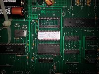
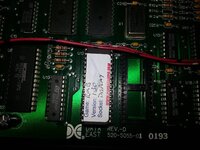
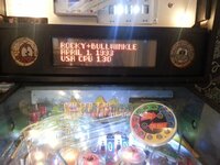
This weekends small job. Received the 1.3 code on chip so removed the old (v1.1) chips and put these in. Another job off the list.

Thanks to Paul for doing the chips for me. :-)


20131019_174522.jpg

20131019_174556.jpg

20131019_174633.jpg

Only bad news was it means the high scores have been reset. Thankfully it didn't take long for me to get back onto the (bottom) of the leaderboard. Had a brilliant game with > 300M on a single ball. Alas the next two balls were terrible but it still yielded 367M which was enough to get spot #6 on the board.

I'm looking at possibly replacing the playfield glass at some point as it's pretty well used with a number of scratches. It's not high priority so it's a way down the list but I started looking into it. Local glaziers tells me that 5mm (which I believe is standard spec for Pins) isn't common and usually made to order so they can only quote me 4mm or 6mm thick. Not sure if that would work so need to investigate further but i'm looking at around £70 for the thicker of the two.

Next job is to remove the side armour on one side and take that, the lockdown bar and leg to the powder coaters to get a price.
 
Returned to do a bit more work on the table tonight.

First up was a really annoying fault which had been happening more and more of late. When the gate at the top left of the playfield was opened by triggering the right orbit triggers the coil and mech on the gate would make a really hideous noise. Like this.


Strangely it had been a bit hit and miss and i'd had the assembly off and on a few times but never really looked at it too closely.

Well tonight I had enough of it and stripped it out entirely. I noticed that the locating 'lug' on the bottom of the coil wasn't sat in the hole correctly which meant it wasn't sat flat against the mounting plate. I stripped the plate off and reseated it before re-tightening the screw that secures it in place. Fitted the whole lot back to the playfield and low and behold no more noise. Hurrah!!

I also removed the B (from BOMB) target and fitted the foam behind it that I got from Andy at Play Expo. It means the target now leans forward slightly so it stops airballs and ensures the target needs a good solid whack from the ball to register. Tried a game out with it in place and the table does play a lot more nicely now. It also seems to stop the issue where a good hit to the target slings the ball SDTM. I'll do the same with the rest of the targets in the next few days.

I've also heard something about cleaning the leaf switches using a business card. Is it really just a case of sliding the card between the contacts to remove and residue that might have collected there? Or is it more complex than that?

Oh, and finally tonight I stripped the flipper button off from one side of the table to see how easily the side rail will come off. Sure enough it was much looser once i'd removed the button (dur!!) but it's clear it's got tape holding it in place so I need to pop tomorrow after work and grab a wallpaper scraper so I can hopefully remove one side rail.
 
:D

I've also ordered the bits needed to make my repro plastics. The shooter cover and the plastic below the Nell Log both have fairly large cracks in them and neither seem to be available any more. Whilst I wait for the parts to arrive I decided to take my raw scans and have a look at how to get the best results from them.

I've used software to vectorise the images before but it's always a bit hit and miss and when I tried it in this case I was left with some nasty ghosting on the images.

So i've decided to go the old school way and started to manually split out the image into it's component parts so I can tidy things up before reprinting them. I realise the image i've used to test is actually one of the plastics you can still get, but it was the first image I came across and I figured it was worth doing just in case the original part becomes hard to get hold of in the future.

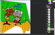
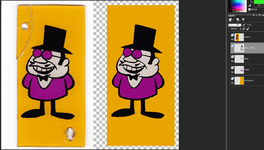
Anyway, pictures. Here's the raw scan.

RockyPlastic_Scan.png

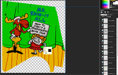
And here's the 'cleaned up' version which is made from a number of layers seperated out. I then touch up each layer to remove the nasty bleeding and anti-aliasing you get along the line edges.

RockyPlastic_Cleaned.png

Still some work to do especially around the edges, but it's coming along quite nicely I think.
 
I'd be interested in seeing a tutorial on how to do this, I work with photoshop every day but I don't know how to split an image down like that.
 
I'll put a tutorial together when I do my next plastic. I just use Paintshop Pro which is a pretty inexpensive product. Think it cost £80 for my copy and it's got all the features I need.

I've just done this one. Took me about 30 minutes to split the elements out and i've now got a relatively clean image with no colour bleed. I might tidy up the black lines a little more but I don't want to stray too far from the original.

Shooter.png

The biggest benefit to splitting the image this way is you can sort the layers so that they overlay correctly. Then it's easy to select one of the 'fill' layers (such as purple or white in the image above) and carefully paint around the edges to make sure the fill is complete. Any over-paint is covered by the thick black lines anyway.
 
Returned to do a bit more work on the table tonight.

I've also heard something about cleaning the leaf switches using a business card. Is it really just a case of sliding the card between the contacts to remove and residue that might have collected there? Or is it more complex than that?

Yes, it is usually pretty much as simple as closing the contacts on a piece of card and gently 'wiping' the contacts. Whatever you do, don't file the contacts; they're gold plated due to the low voltage/current that they handle.
 
Thanks Jay. I'd heard the same elsewhere too.

Worth doing whilst i've got the targets out anyway. :-)
 
If you could do me a scan of Nell from the plastic on the log that would be great - if you could split it up (or send me the instructions) that would be even better!

I've been trying to clean up a low resolution cut from a photo from IPDB (or ebay), it's better than no plastic, but I can't see it getting as good as the examples you show in this thread!
 
I already have a scan of Nell but i've not split it into elements yet which means she still has some rivets visible in the image.

Leave it with me and I should be able to post a suitably split image tomorrow. :-)
 
I'm looking at possibly replacing the playfield glass at some point as it's pretty well used with a number of scratches. It's not high priority so it's a way down the list but I started looking into it. Local glaziers tells me that 5mm (which I believe is standard spec for Pins) isn't common and usually made to order so they can only quote me 4mm or 6mm thick. Not sure if that would work so need to investigate further but i'm looking at around £70 for the thicker of the two.

Nooooooooooooo - don't listen to the glaziers. 5mm toughend is available; it is a special order but glaziers can get it. You should be able to get a glass for less than £30. We clubbed together locally and ended up paying £24 for standard size.
 
Its not urgent so it can wait anyway. As it happens I might have to head down to Rugby at some point in the future so if that happens I could get a replacement glass from Andy Legend.

As I said its at the bottom of a long list and it will be one of the last things I do. i want to strip the cabinet and get it nicely tidied up first.
 
you star!

I can see if I can get a shot of the spring for you in exchange, at least you will know how many windings it has (assuming mine has one - not got as far as having Nell move yet)
 
No problems macro, I already have a lot of information on the spring. FirebrandX over at Pinside posted a nice picture with measurements.

I have found a company that can make me a spring but its a bit pricey. Im going to order a correctly sized dowel and spring wire and have a go at making my own.

Thanks for the offer though. :)
 
Managed to spent a little more time working on the table yesterday. First up was getting the foam fitted behind the BOMB targets. This pretty much eliminates air balls and ensures that the targets need a good hard whack to register the hit. It also removes the situation whereby the target can be triggered multiple times by single strike.

Anyway, pictures.

First up heres one of the targets after i've dropped it below the playfield. Interesting hu? ;)

Targets_Refoam_1.jpg

Next job was to seperate the metal supports away from the target itself.
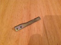
Targets_Refoam_2.jpg

The supports on a couple of the targets were pretty badly bent. I used two pairs of pliers to straighten them out but i'll have to keep an eye on the and see if the foam makes an difference. I've heard that once bent they bend again much more easily and if that happens the only answer would be to replace the entire post.

Anyway, I affixed the foam to the top of the post.
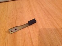
Targets_Refoam_3.jpg

Whilst I had the target off the playfield I also cleaned the contacts using a business card. Then I reaffixed it back in place and tested. It's suprising how such an easy fix can make the table play so differently. Each target now requires a good hit to register but it also seems to have remedied a situation where the balls would regularly bash a target and then shoot SDTM. So although it's been made a little harder by the strength of shot required it also seems much fairer.
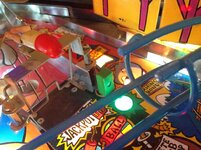
Targets_Refoam_4.jpg

The next job on the list was to strip one of the side rails so that I can take that, along with the back box brackets, lock down bar and legs to the local powder coaters. It turns out we actually have two in town so i'll go to both to get prices. The intention is to have the lot shot-blasted and then re-powder coated in red. Means the table won't be original in terms of colour scheme but as I don't intend on selling i'm not really that fussed; and to be honest I think it'll look much nicer in red (perhaps with yellow flipper buttons?).

I'd never removed the side rails before but I took Andys advice and removed the fixtures before using a paint scraper underneath to break away the adhesive tape used to hold it in place. Only took a few minutes and i'd managed to strip both parts off the machine with no damage to the artwork. There's a lot of the adhesive tape left on the machine though and it's a pain in the backside to remove; it strips off in small pieces so it's going to take a while to clean it off. I don't really fancy using anything too aggressive in case it damages the paintwork.

So here's the stripped rail.
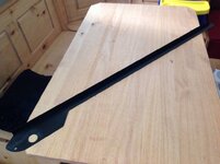
SideRailStrip_1.jpg

And the cabinet. I've put the glass back in for now so I can still play it. Will head to the powder coaters tomorrow after work to see how much i'm looking at.
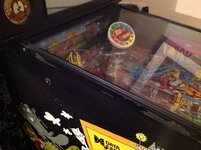
SideRailStrip_2.jpg
 
Back
Top Bottom