Hi, Will,
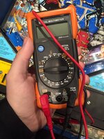
Firstly, the leads aren't in the right sockets; the black lead should be in the 'Com' socket, while the red one is only used in the 10A socket to measure on the 10A scale. Mostly it's used in the r/h (Volts/Ohm/diode) socket.
Then you need to select what range to use. Going clockwise, there are 2 Ac voltages ranges, 5 current ranges (including the special 10A), diode tester, continuity beeper, 5 resistance Ohm scales and 5 Dc voltage ranges.
Dc voltages are measured against Ground, with the black Com lead placed on Ground and the red lead on the component/pin/lead/trace to be measured.
Resistances are measured with the device power Off. The two leads are placed one each side of the component and the resistance between is shown. But the results can be skewed by other, unwanted, parallel circuits unless the component is in a simple circuit, or removed (even partially) from its usual circuit.


