What's new
Pinball info

Register a free account today to become a member! Once signed in, you'll be able to participate on this site by adding your own topics and posts, as well as connect with other members through your own private inbox!

In Progress Node board repair

Not sussed those ones out yet, there's a bit of a long queue here -- been prioritising those that aren't mine 😅
No worries 👍

Well one of them probably doesn't have a fault I think it was the actual pins on the connector block, be interesting to know, (dont worry I don't care if it works fine 👍)
The other acting as node 9 is definitely a cap issue not holding its charge to start the board I suspect, as it will work once machine on for a bit and a charge has been put through the cap, quick turn off and on again works perfect, until powered off for a bit.
 
So - Question. I have a faulty None 9 board somwehere for GB. My machine is fine - picked it up as a "faulty spare" just in case.
Is there any realistic chance of damage if i through it into mine for fault finding, at the very least to try to work out what the current status is before starting a repair?
 
Is there any realistic chance of damage if i through it into mine for fault finding, at the very least to try to work out what the current status is before starting a repair?
Not impossible but minimal chance to cause any damage I would think unless the "faulty" symptoms include black smoke coming out of the machine. 😂

You can do a standalone bench test by supplying the 48V rail and putting 9V or so across the VNB rail on the RJ45 connectors. If red & green lights come on, and the orange one flashes, the power is good and the MCU is alive. See post #34 in this thread on page 2.
 
Hey @Fubar @myPinballs have you ever worked on a QR reader board? Got an interesting one with my GOTG whereby the QR reader appears to be working as normal (and sometimes does), but most of the time doesn't show up in the node board test despite the blue light being on, the yellow light flickering and the read light coming on when I show it a QR code.

The times I've had it working are usually in the couple of minutes after powering on the machine, and it'll work briefly, but after that it stops and board 4 shows as 'not responding'. I've tried different cat5 cables (despite them testing OK), and tried plugging it directly into the CPU board in multiple sockets but can't get any reliable behavior out of it.

It feels like a loose/broken connection somewhere, but I'm not sure where to go other than just reflowing the RJ45 socket for the hell of it 🤷‍♂️
 
@ChriX never worked on one of these. How is yours wired to the CPU - is it daisy-chained off one of the under-pf boards, or does it go direct to the CPU?

One thing I noticed is that these QR boards (node 4) must be powered from the 9V "VNB" rail. Technically it's a 3A supply however just 2 wires in a CAT5 cable aren't going to carry much current over a 2m run... It's a shame they haven't released the schematics for this QR reader board.

Your problem sounds more like a comms issue however. Perhaps try plugging it direct into the CPU using a short cable, see if that solves the problem? Otherwise it must be something wrong with the board itself.

Edit: nevermind just noticed you said you did try plugging it direct in the CPU - doh! Sounds like a dodgy board then, maybe try reseating the ribbon cable on it?! Just looked and spares go for a meager $175 !! 😱
 
Last edited:
Yep, reseat the extra small ribbon cables on it that link the two boards together. It helps to have a magnifier and tweezers to hand. The ribbon cables are extremely easy to catch on, slightly (or fully) knocking them out of the connector.
 
Thanks for the input guys, just tried the reseating ribbon cable suggestion but no change in behaviour.

I'm wondering if the green board with the camera on it is an off the shelf part, and the node board on the back interfaces that to the game, so now thinking if the 'read' LED lights when I show it a QR code as it does, maybe the front board is fine and the problem lies with the rear one.

My gut feel is that it's receiving and not transmitting, as the LED is flickering to show the bus activity, but obviously nothing else is happening - maybe similar symptoms to the board that seems to be running but not responding to the CPU earlier in the thread. 🧐

Agreed it's annoying there's no schematic but I'm wondering if they use a similar structure for the communication setup, although at first glance there don't seem to be any optoisolators. I'll continue poking around, it's worth a go, $175 for a new one is a bit of a **** take!

IMG_3853.webp
 
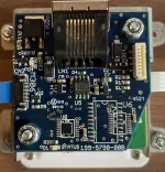
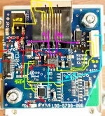
I did a bit of amateurish reverse engineering - the structure of the comms circuit does look similar to the other nodes, but without the optoisolators. The micro seems to be directly connected to a logic gate for TXEN, which is directly connected to the transceiver. I wonder if in the absence of any other ideas it's worth swapping out the transceiver and/or nand gate.

What I did discover is that the 'READ' LED signal seems to be coming from the camera board rather than the microcontroller on the node board, so doesn't really give us any indication that the micro is working correctly.

Screenshot 2024-10-02 at 13.20.30.webp
 
Thanks for sharing your analysis! Do you have a scope to look at the data lines?

Also wonder if it's worth testing with all the other node boards disconnected from the bus?

Finally I don't suppose you have another QR reader handy to cross-test?
 
I haven't yet invested in an updated scope or logic analyzer, I'm still rocking a CRT one which isn't much use here 😅

Would you believe it after poking at it with the multimeter figuring things out and comparing it to the schematic of the other boards, the thing is working! Gotta love intermittent problems. I wonder if it's as simple as a dry solder joint somewhere, or maybe you guys were right with the ribbon cable, and I just didn't do it right the first time but got it when I took it all apart to probe.
 
So I just spent an evening looking at how the flipper coils are driven on my TMNT v1.55. Maybe some nerds on here will be interested, worst case I have some notes somewhere 😄

The delay from button press is around 2.5ms. Initial pulses at 17.35 kHz for around 36.385ms, where the flipper power setting linearly affects the duty cycle, then a hold pattern which is the same frequency but about 12% duty cycle.

I wonder how that compares to other brands - of course WMS pins will have the EOS switch which means there'll be no PWM going on.
 
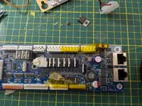
Today we have a success story! It can be frustrating working on these boards as sometimes after hours of diagnosing and changing parts it still won't work... But in this case we got lucky! :D

This fault is also the most common one: I've seen it twice myself and there are many reports of it on the internet.

Symptoms are only the red LED comes on (48V), not the other green (6V) and amber (MCU activity) ones.

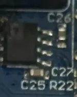
Cause is the MBR760 (D9) and MP24943 (U9) components burning out.
Replacing both is a PITA however due to the ground pad on U9 and general cramped location, but with a hot air station it can be done.

PXL_20250127_205518083.webp

And with that, this guy will be going back to its owner tomorrow :)
 
Today we have a success story! It can be frustrating working on these boards as sometimes after hours of diagnosing and changing parts it still won't work... But in this case we got lucky! :D

This fault is also the most common one: I've seen it twice myself and there are many reports of it on the internet.

Symptoms are only the red LED comes on (48V), not the other green (6V) and amber (MCU activity) ones.

Cause is the MBR760 (D9) and MP24943 (U9) components burning out.
Replacing both is a PITA however due to the ground pad on U9 and general cramped location, but with a hot air station it can be done.

View attachment 270462

And with that, this guy will be going back to its owner tomorrow :)
Add the cable tie and spacer on diode to the nearest mosfet aswell. Brings it to current stern spec . Not sure it really does anything but anyway..

I find the removal of the main filter cap also helps sorting them out giving you more space.

But anyone attempting this, dont do it unless you know how to remove thermal pad voltage regulators safely without destroying the board. Anyone sending me one with the ' i tried myself first ..' gets the standard reply 'throw it in the bin' :)
 
Add the cable tie and spacer on diode to the nearest mosfet aswell. Brings it to current stern spec . Not sure it really does anything but anyway..
Thanks, yes I did put those back on after snapping that photo.

Someone also suggested replacing the diode with a MBR780 which is good to 80V instead of 60. Don't if it helps but guess it can't hurt.
 
Thanks, yes I did put those back on after snapping that photo.

Someone also suggested replacing the diode with a MBR780 which is good to 80V instead of 60. Don't if it helps but guess it can't hurt.
Dont think that makes any difference other than maybe ease of getting parts... it's the regulator that cant handle it anyway and takes out the diode as far as i know. absolutely **** design!! when you think its 48v dc into that tiny regulator. and it has to drop to 6v. no wonder it kills itself...
 
Are you preheating or just hitting it with hot air? No more Kapton than what you show on the image?
 
Are you preheating or just hitting it with hot air? No more Kapton than what you show on the image?
Just what's on the picture, mainly to protect the plastic connectors. Preheat both sides of the PCB at 120C for a minute or two, then 350C on the regulator should free it in less than a minute. I'm using a Quick 861DW hot air station.

The diode came out first, with just snips and a soldering iron. I like to think that kind of preheats the ground plane a bit?
 
Could be, never worked on one of them. I generally Kapton all around the chip, preheat and blow it off with an ERSA Icon - mostly microwave stuff.
 
Back
Top Bottom