OP
OP
The CPU being waiting for parts, I return to the cabinet node worked on previously. As a reminder, some kind of damage had happened around the NAND gate controlling the TXEN signal of the node bus. Whilst I had managed to hack it back together with the original chip, I had the feeling that it wasn't very robust, and I didn't really trust that chip either as it may well have been the cause of the damage! I wanted to write a bit of software to test the bus. Couldn't immediately find an echo command so I settled on just querying the switches 20 times per second.
Now I forgot to capture the log at the time, but basically it was flaky. Sometimes the data would read correctly and then after a random interval (tens of seconds) the line would turn to garbage, returning 0x55EEEEE5555EEE5E5E5E55E5EE... This is consistent with the TX enable signal not registering. I probed it a bit and tried to patch things back together but it was too far gone and quite frankly in a right mess!

So I decided to replace the chip with a new one, which posed 2 problems: (1) the original footprint was destroyed beyond repair (fubar), and (2) the replacement chip I got had an even smaller footprint, being SOT353 instead of SOT23-5 (that's down to 0.65mm pitch - yay).
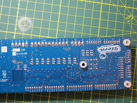
For the first problem I had got a breakout board which unfortunately used the larger footprint but it was close enough to work. I transferred the decoupling cap onto there although due to the pinout had to use a wire, still better than nothing I guess. Used a short length from a cut pin to bridge the 2 inputs together as on the schematic, this will let me wire that net to both the source IC as well as the pull-up using separate wires. On the left you can see the cleaned up footprint and also were I cut the traces in case there was any funny business going on where the IC used to be.

Here's a closer look. Not pretty. You can see on the left where I scratched the soldermask away to make a ground pad. The dumbells on the right is our VIN, and we'll also be reaching to the resistor above which is the input pull-up. The 2 remaining connections will be directly to the legs of the partner ICs.

With that I proceeded with the enfuriating task of stripping very short, thin gauge wires, at both ends and created a little spider. I then fixed the board using CA to some kapton tape on the conveniently-placed RJ45 jack, and soldered all the tentacles to where they needed to go. A couple of them broke and I had to remake some of these horribly fiddly wires...

This is obviously quite fragile especially against a handling point like the ethernet jack so I will add some mechanical protection asap (hot snot). But first it needs a test! This time I did remember to capture the output...

Notice the orange wire jumping 2 pins together: these are GND and PLUMBTILTSW. This lets me fake a tilt and is the cause of the bit toggling seen in the output above. We can even check this using a game manual:

Switches are numbered from 0 and (1<<22) = 0x40_0000. Now we're running on a 32-bit little-endian system (iMX6) and my silly program is printing the data as a u64, indicating that we're seeing a change of bit 0x40 in byte[1], which suggests a big-endian u32 representation. That doesn't make a lot of sense so I've probably got something wrong - endianness always makes me confused!! (And it's late !)
!)
To end on a more useful note, how did I know which pins to bridge for that switch? Here's a handy dandy reference pinout which seems to be somehow absent from the official online docs")

Much happier with the state it's in now. As I said it needs a bit of protection - will use some hot glue, tape and maybe a bit of liquid rubber. But that's enough for tonight - it's time to enjoy a few games on Getaway!
C:
int main(int argc, char** argv)
{
  if (argc < 2) {
    printf("Usage: %s node_id\n", argv[0]);
    return 255;
  }
  int node_id = strtol(argv[1], NULL, 10);
  if (node_id < 1 || node_id > 15) {
    printf("Invalid node id: %d\n", node_id);
    return 1;
  }

  if (NODEBUS_Restart())
    return 2;

  uint64_t prev_state = 0;
  uint8_t  last_poll = 0;
  struct timespec last_change = {};
  clock_gettime(CLOCK_MONOTONIC, &last_change);
  while (1) {
    uint8_t poll = NODEBUS_Poll();
    if (poll != last_poll) {
      printf("Poll %d\n", poll);
      last_poll = poll;
    }
    uint8_t data[INPUTSTATE_BYTES];
    int rc = NODEBUS_GetInputState(node_id, data);
    if (rc != 0) {
      printf("GetInputState failed with %d\n", rc);
      return 3;
    }
    uint64_t state = *(uint64_t*)data;
    if (state != prev_state) {
      struct timespec now = {};
      clock_gettime(CLOCK_MONOTONIC, &now);
      float diff = diff_ns(last_change, now);
      printf("Node %d input state: changed from %llx to %llx after %f sec.\r\n",
             node_id, prev_state, state, diff / BILLIONF);
      prev_state = state;
      last_change = now;
    }
    usleep(50000);
  }
}
Now I forgot to capture the log at the time, but basically it was flaky. Sometimes the data would read correctly and then after a random interval (tens of seconds) the line would turn to garbage, returning 0x55EEEEE5555EEE5E5E5E55E5EE... This is consistent with the TX enable signal not registering. I probed it a bit and tried to patch things back together but it was too far gone and quite frankly in a right mess!
So I decided to replace the chip with a new one, which posed 2 problems: (1) the original footprint was destroyed beyond repair (fubar), and (2) the replacement chip I got had an even smaller footprint, being SOT353 instead of SOT23-5 (that's down to 0.65mm pitch - yay).
For the first problem I had got a breakout board which unfortunately used the larger footprint but it was close enough to work. I transferred the decoupling cap onto there although due to the pinout had to use a wire, still better than nothing I guess. Used a short length from a cut pin to bridge the 2 inputs together as on the schematic, this will let me wire that net to both the source IC as well as the pull-up using separate wires. On the left you can see the cleaned up footprint and also were I cut the traces in case there was any funny business going on where the IC used to be.
Here's a closer look. Not pretty. You can see on the left where I scratched the soldermask away to make a ground pad. The dumbells on the right is our VIN, and we'll also be reaching to the resistor above which is the input pull-up. The 2 remaining connections will be directly to the legs of the partner ICs.
With that I proceeded with the enfuriating task of stripping very short, thin gauge wires, at both ends
and created a little spider. I then fixed the board using CA to some kapton tape on the conveniently-placed RJ45 jack, and soldered all the tentacles to where they needed to go. A couple of them broke and I had to remake some of these horribly fiddly wires...This is obviously quite fragile especially against a handling point like the ethernet jack so I will add some mechanical protection asap (hot snot). But first it needs a test! This time I did remember to capture the output...
Code:
root@stern-spike2:~# ./monitor_inputs 1
Scan: node 0, next 1
Scan: node 1, next 0
Node 1 input state: changed from 0 to ffffffffffffbf9f after 0.002818 sec.
Poll 1
Node 1 input state: changed from ffffffffffffbf9f to ffffffffffffff9f after 3.972641 sec.
Poll 0
Poll 1
Node 1 input state: changed from ffffffffffffff9f to ffffffffffffbf9f after 4.981831 sec.
Node 1 input state: changed from ffffffffffffbf9f to ffffffffffffff9f after 0.053427 sec.
Node 1 input state: changed from ffffffffffffff9f to ffffffffffffbf9f after 0.053425 sec.
Poll 0
^C
Notice the orange wire jumping 2 pins together: these are GND and PLUMBTILTSW. This lets me fake a tilt and is the cause of the bit toggling seen in the output above. We can even check this using a game manual:
Switches are numbered from 0 and (1<<22) = 0x40_0000. Now we're running on a 32-bit little-endian system (iMX6) and my silly program is printing the data as a u64, indicating that we're seeing a change of bit 0x40 in byte[1], which suggests a big-endian u32 representation. That doesn't make a lot of sense so I've probably got something wrong - endianness always makes me confused!! (And it's late
!)To end on a more useful note, how did I know which pins to bridge for that switch? Here's a handy dandy reference pinout which seems to be somehow absent from the official online docs
Much happier with the state it's in now. As I said it needs a bit of protection - will use some hot glue, tape and maybe a bit of liquid rubber. But that's enough for tonight - it's time to enjoy a few games on Getaway!


 Well at least we've found
  )
)


") The first one being the 8-coil pf node which had the failed cap, and the second the CPU board with failed backbox lights. Do you have broken node boards at home too? Let's chat!
The first one being the 8-coil pf node which had the failed cap, and the second the CPU board with failed backbox lights. Do you have broken node boards at home too? Let's chat! 


 There is continuity from these pads to the processor's pins and no visible damage to the board so not likely to be a trace. I decide to test just the processor's UART in isolation. Maybe one day I'll build a bed of nails, but for now 6 spots of solder will have to do...


