What's new
Pinball info

Register a free account today to become a member! Once signed in, you'll be able to participate on this site by adding your own topics and posts, as well as connect with other members through your own private inbox!

myPinballs Custom Bally Pinball Controller in Development

Have you got any photos, vids or info about what you're doing? Sound interesting!

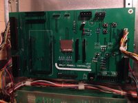
nothing huge; right now I am respinning the boards to use rs485 and turning the 32solenoid driver board into an 8, so I can drop in as few or as many as I need onto the bus. (latency is non existant, 1.5ms to transmit the 128switch state to the boards). master board has 128 direct switches on it, feeds child boards (solenoids/flashers, inserts, etc). all a/v commands go to the raspi which has a usb dac to a car amp doing stero + sub (might change that out to something less beefy and less power hungry). all open source software, open hardware schematics etc.

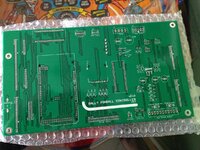
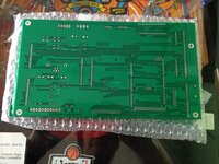
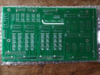
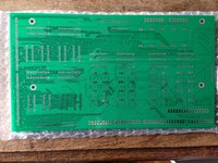
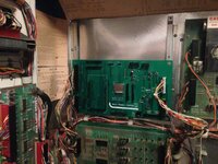
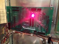
some old pics of the existing boards;

old RGB insert board (changes not show, dual rj45 jacks for rs485 bus). Does 64 RGB led's for inserts (the FastRGB LED modules from FastPinball which are ws2811's on a stick, very nice).
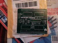
i.imgur.com_eFp8qm5.jpg

32x solenoid driver (or flashers etc), changes not seen here going to the fab next week are its more like the original prototype at doing 8x standalone.
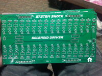
i.imgur.com_QDJhJLN.jpg

Apologies to MyPinballs for spamming my stuff into his thread.
 
nothing huge; right now I am respinning the boards to use rs485 and turning the 32solenoid driver board into an 8, so I can drop in as few or as many as I need onto the bus. (latency is non existant, 1.5ms to transmit the 128switch state to the boards). master board has 128 direct switches on it, feeds child boards (solenoids/flashers, inserts, etc). all a/v commands go to the raspi which has a usb dac to a car amp doing stero + sub (might change that out to something less beefy and less power hungry). all open source software, open hardware schematics etc.

Apologies to MyPinballs for spamming my stuff into his thread.
Nice project. On my revision 1 board the rgb lamp control (off screen on the vid) was designed for WS2801 ics . The rev 2 board is designed for the WS2811 Led/Ics so the fast led boards can be used on this setup and it saves 1 I/O line.

Best to start your own thread if you want to discuss your project, thoughts and roadmap. Careful though, you'll need a thick coat on and bullet proof vest ;)
 
I think the point is he is making money from other's hard work. Taking but not giving.

So then, this........ Hmmmmmmm

I would like to point everyone to the following article that was written recently by a masters student who contacted me about some possible work placement after seeing the kind of work my business is undertaking.

http://jonosandilands.blogspot.co.uk/2015/02/mypinballs-intro.html

I invited him to see what i was doing and spend 3 days with me. It was a very enjoyable and rewarding experience. As other's have also mentioned I have given up time in the past to run hacking labs at shows and demo open source game rewrite projects as a means to inspire and create interest in this area of pinball. I do this as i have a genuine interest in the subject and want to share my knowledge and experience with others. I do run a business though yes, so it needs to make money to keep all these activities and projects afloat. I do not apologise for that. And to be clear on show games, I have given multiple games to every daventry and nlp show since they began.

To just blurt out random comments about people and their businesses without knowing the first thing about them is just plain ignorant and rude. You should issue an apology for your conduct on here and your comments towards my business. I would now like to continue with my projects and innovations.

All my projects including the open source ones are found on my website mypinballs.co.uk
 
Second revision controller board now with the manufacturers. Should have them back in a few weeks, so assembly can start. Also have been working more on the code base and have split the main file up into separate sections, much more like the organisation i use in p-roc projects. Much easier to work on. Switch matrix functionality is been fine tuned and response looks good from the loop speed. There are 4 states reported from a switch. Active, Held, Inactive, Idle. Depending on other projects and board delivery I will aim to bring something to 8bit flip to show progress and how the code base is organised for interested parties. The new driver board is in the layout stage and i'm hoping to get that complete this coming week.
 
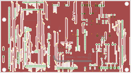
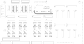
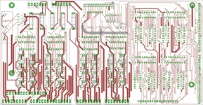
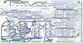
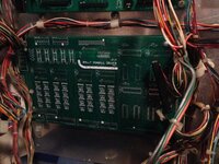
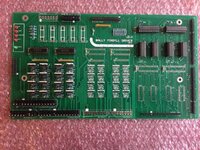
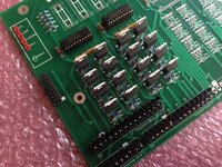
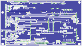
Some pics of the first pass at the driver board. The cool thing here is that there will be 16 extra high power drives for adding flashers, motors etc and other new add ons to a game, aswell as 4 extra low power drives. The total drives are 32 high power and 64 low power.

Bally Pinball Driver v0.2 compnent layout.png Bally Pinball Driver v0.2 toplayout.png Bally Pinball Driver v0.2 bottom layout.png
 
Last edited:
Some pics of the first pass at the driver board. The cool thing here is that there will be 16 extra high power drives for adding flashers, motors etc and other new add ons to a game, aswell as 4 extra low power drives. The total drives are 32 high power and 64 low power.

So will the driver board be plug and play for the drives which are already in the machine? The existing drives are on the power supply board if my memory works properly, I guess that board will then stay but the drives on it will be unused?
 
So will the driver board be plug and play for the drives which are already in the machine? The existing drives are on the power supply board if my memory works properly, I guess that board will then stay but the drives on it will be unused?

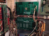
Yes, the board is designed to plug into the existing wiring, as the controller board is. This board will install in place of the old lamp driver, in the top half. So it will be below the controller board. You leave the old power board in place , but move the drive connectors over. The existing lamp connectors plug straight on to. The new board also allows a 'fliptronic' control approach for the flipper mechs, which improves the power and responsiveness of them greatly (as demoed at play expo). I wanted to create something that goes beyond just driving the old boards so that there is more scope for innovation and improvement over the original. The additional drive outputs provide options here and you can still use the factory solenoid expander setups to.
 
Dude. Sent you a message on Friday and also posted in your P2K thread. Drop me a reply please.
 
Worked out the final few bugs in my PinballDisplay class tonight and have a slave arduino now controlling a full set of displays. This means that the system can be configured to run original displays (via the display arduino) or use more modern serial segment displays via the onboard display connector.

Pic attached from my ElektraIMG_3695.JPGIMG_3696.JPG
 
Testing the slave audio and display control from the master controller. Also making some refinements to the onboard amp circuit now some more TDA2003A ics have arrived.

IMG_3736.JPG IMG_3739.JPG
 
Update: Started the transfer of the board set over to my high voltage custom game now i have the boards built to a useful point and i have a fair amount of testing code written. I also reworked the main code base for use with high voltage. My HV game was built 20 years ago or so before i knew much about electronics, or programming and so was a retheme and new layout of futura spa. Now, finally i get to create a new set of rules, sounds and control for it. :)

HV will form the base of the new test bed and i aim to recreate the ruleset and then add onto it.

IMG_3751.JPG
 
Update: Got the new driver board and controller board talking last night and have coils and lamps working. Will shoot a quick video later. Continuing the development of the framework to for control of feature items in bally pinball games and lamp effects. A few bugs to sort out, but moving forward nicely.
 
New video up here:


Showing basic game play with jets, slings, kickback, saucers etc. There is sound also on the events but may not be that audible on the video as i still have some work to do on the amp section.

So, these tests help to confirm correct operation of the driver board and controller board together, as well as the response from the switch matrix and how the mechs feel. Each switch is tied to a method which is called when the switch is activated/deactivated. As well as this there are a series of lamps being controlled at the same time. In the video they are flashing on and off during the game play. As the driver board is an updated version of the first revision i wanted to make sure everything was working correctly before going much further with the framework. The lamp control section is using some new maxim chips i sourced which are serially driven. I am thinking that using leds only for lamp inserts would make the driver board component count quite a bit simpler to and hence keep the cost down, so have been experimenting with this to

Cheers, Will post another vid with flippers connected up once i finish up a few things inc. the ground flipper switch connection. Hope you all enjoy the vid. :)
 
New video.


Worked out the flipper connection setup, so the boards now plug in and flipper control is neatly taken care of. Some of the tricky part was making sure it was a fliptronic setup and not just using a relay like the old days, but without needing to alter any of the existing wiring or connectors. Job done!

So the video show basic game play, game start, end of ball etc and of course the coil control from before. You may also notice some additions in the lamp section. Basic lamp attracts are shown before game start then cleared and lamps lights based on the bonus you are collecting. I am only using a few lamps currently as am waiting for more led bulbs to come, but is proof of the new lamp system setup and control. I will be getting the rest of the lamps working soon. Also looking at sorting the bugs in the amp section so can have nice loud sound to
 
Update: New Video with basic sound now working.


I got to the bottom of what was up with the sound hardware. I had a couple of mistakes on the design and needed to adjust the sensitivity of the sound level input. The amp setup using a TDA2003A is taken from my s&t board design which has a gain of 101. Arduino's output 5v to 0v for a PWM signal and so a voltage divider is needed to set the level accordingly. I also needed to add some filtering components to set the high level frequency cut off and some other filtering stuff.

I'm also working on some improvements to the sound controller software framework now i have the basics working and also experimenting with how the sound files are exported so see what the best quality is. I haven't set up the second channel set, so everything is just 1 channel as the moment.

IMG_3808.JPG
 
Update: So a lot has been going on with the sound controller and amp hardware. I wasn't happy with the first set of results, so i went back to the design and improved it again an now i have the sounds really sharp and the amp hardware set up correctly for the line level and inputs it expects. ON the last video, certain sounds were actually distorting, though i didn't realise at first and the volume level was not set to the best of the amps abilities. Once it starts to distort the actual volume decreases in real terms. So now i'm pretty certain i'm getting the most out of my little TDA2003A. The volume levels are now comparable to that of the s&t board so that also makes me happier.

As well as working on the hardware side, i had to talk with the writer of the sound control library, as some changes were needed to the internal buffers set for use on the nano hardware. Further more i created a load of new better sounds ( 32Khz, 8 bit, mono) and with the correct recording level. The next thing to do now i've tested all this is to implement the 2nd channel. Really liking the sounds for coin up and game start (see vid)

Check the video out below and see what you think of the new refined sound setup.

I've also been working on the driver end and now have connected up the second set of 16 lamp drives, so i have 32 working in the video. I have also done a quick led swap out on the playfield so now you should be able to see the 32 lamps strobing in attract. The pattern is set to be very fast to show the additional power of the system compared tot he original board sets. More effects will be added as i get further on and of course the other 32 lamps.

I have also been improving /fixing bugs in the game framework and game modes. You should see better feature control starting to appear now. Check the lamps on the kickback etc for progress and the centre triangle for collected triangles adding to the bonus etc.


So, a lot has been going on recently and have some major updates to share along with some new videos. Update summary:

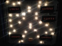
  1. Displays are now syncing in attract showing high scores and previous game scores.
  2. Sound system is now working with 2 channel. Currently upgraded to use another mega for sound as additional ram was needed to run 2 channels reliably. Single channel worked fine on a nano. Also thinking about integration to wav trigger types boards as alternative, but would really like to keep the arduino for sound to as is lower cost.
  3. Full 64 lamps now working. Had some long evenings over the weekend tracing some bugs, which turned out to be some wrong pin refs for enable lines. All pretty obvious once realised what was happening. Check the attract video out for some seriously nice patterns. Note that the ramp lamps are strobing quicker than the other areas, as an example of how you can expand and control the patterns. This concludes the testing of my new driver board and confirms the technology works really well.
  4. Rule development has been progressing using my framework and software api nicely. I have a new video shooing some of the rules now in place from the original game. You can see how switch events are handled and how rules are built up along with showing how lamps and coils are controlled.


Quick Update: I made a tweak today to the display controller framework to solve a small ghost issue i was having with the displays. The previous digit was ever so slightly visible in the next digit along on the display. This was tracked down to the digit enable lines being turned high before the binary number was latched in to the decoder. Swapped those 2 events around and now the displays are really crisp :) I've also made improvements to the score methods in the game code and scoring is working really nicely now to.
 
Back
Top Bottom