Pinball info
You are using an out of date browser. It may not display this or other websites correctly.
You should upgrade or use an alternative browser.
You should upgrade or use an alternative browser.
In Progress Mishmash Homebrew - Pt II - Playable Coffee Table
- Thread starter Ashbo
- Start date
Ashbo
Site Supporter
Nice.
Ashbo
Site Supporter
A week and a half since my last update- what has changed? Materially, not a lot, but beneath the surface, loads and loads. (Code here)
We now have full editing of the switches and coils which are created in JSON and stored in SPIFFS and loaded at boot time to update the switch and coil global objects.
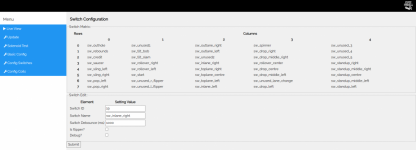
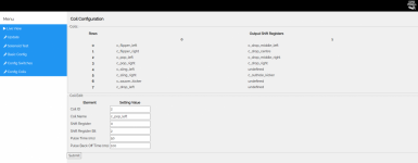
Next task will be to create the GUI elements that will allow for coil to switch binding.
I will then shift my attention to the GUI for LED definition and control, then to sound effect audio (video and music probably from a PI Zero connected over serial)
Following that, it may well get exciting as we will start coding the GUI to edit the rules and define the modes. It would be easy to think this is turning a corner but it's a lot of work yet to do, given the path I have chosen to take.
We now have full editing of the switches and coils which are created in JSON and stored in SPIFFS and loaded at boot time to update the switch and coil global objects.


Next task will be to create the GUI elements that will allow for coil to switch binding.
I will then shift my attention to the GUI for LED definition and control, then to sound effect audio (video and music probably from a PI Zero connected over serial)
Following that, it may well get exciting as we will start coding the GUI to edit the rules and define the modes. It would be easy to think this is turning a corner but it's a lot of work yet to do, given the path I have chosen to take.
Ashbo
Site Supporter
So nearly a month has passed since my last update - much has changed, not that it's too much progress towards actual pinball.
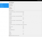
Let's look at the GUI menu to give a hint to the functions that have been added.
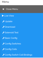
Live View was here before, but lots of manually configured stuff that is now dynamically generated based on later settings.
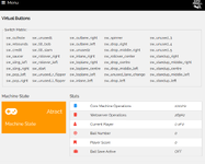
Update - as you were, not much changed here except limiting the choice of .bin files being uploaded.
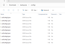
Download - loads of work done here. Basically, all of the JSON files stored in the SPIFFS get scooped up and zipped for download. This means all the work done in configuring switches, coils, bindings and will be done in rules in future developments - these can all be exported and manually copes onto the SPIFFS of another ESP32 board. To DO - upload configs to SPIFFS via the browser.
Solenoid Test - looping through the coils and firing them one at a time in order.
Basic Config - as per last post
Config Switches - extended since the last post. Now we add isStart, isCredit and isOuthole. To Do - add isTrough, but not needed in my single ball playfield just yet.
Config Coils - no additional dev done.
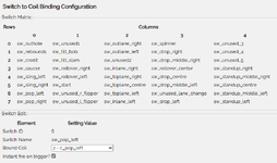
Config Switch Coil Bindings - This is where we can set up how coils are relates to switches. In the example below, we fire off a pop bumper immediately when the switch is hit.
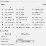
We also can have a coil bound to a switch, like an outhole - but we will leave the firing events to the rules (or "code").
Once all that had been done, I have removed loads of manual code which will later be replace by rules.
So, following advice received earlier in this log - I have implemented an interrupt timer to ensure switch matrix is read once a millisecond - so 1000 times a second - this works very nicely.
I then got to the point of implementing an interrupt on the flipper switches, now this opened up a HUGE can of worms my inexperience was not prepared for. Whereas previously Alan's flipper button design handled switches nicely, it seems interrupts can be very challenging because switch presses and release events can be a real art to detect and not doing so efficiently can really break things by taking up too much processor time and crashing the ESP32 - this needs much more work and more electronics (pull down resistor - at least) than is on v1 of the PCB.
Let's look at the GUI menu to give a hint to the functions that have been added.

Live View was here before, but lots of manually configured stuff that is now dynamically generated based on later settings.

Update - as you were, not much changed here except limiting the choice of .bin files being uploaded.
Download - loads of work done here. Basically, all of the JSON files stored in the SPIFFS get scooped up and zipped for download. This means all the work done in configuring switches, coils, bindings and will be done in rules in future developments - these can all be exported and manually copes onto the SPIFFS of another ESP32 board. To DO - upload configs to SPIFFS via the browser.

Solenoid Test - looping through the coils and firing them one at a time in order.
Basic Config - as per last post
Config Switches - extended since the last post. Now we add isStart, isCredit and isOuthole. To Do - add isTrough, but not needed in my single ball playfield just yet.
Config Coils - no additional dev done.
Config Switch Coil Bindings - This is where we can set up how coils are relates to switches. In the example below, we fire off a pop bumper immediately when the switch is hit.

We also can have a coil bound to a switch, like an outhole - but we will leave the firing events to the rules (or "code").

Once all that had been done, I have removed loads of manual code which will later be replace by rules.
So, following advice received earlier in this log - I have implemented an interrupt timer to ensure switch matrix is read once a millisecond - so 1000 times a second - this works very nicely.
I then got to the point of implementing an interrupt on the flipper switches, now this opened up a HUGE can of worms my inexperience was not prepared for. Whereas previously Alan's flipper button design handled switches nicely, it seems interrupts can be very challenging because switch presses and release events can be a real art to detect and not doing so efficiently can really break things by taking up too much processor time and crashing the ESP32 - this needs much more work and more electronics (pull down resistor - at least) than is on v1 of the PCB.
Ashbo
Site Supporter
Wow, nearly two months since my last update. Thats tardy!! 
Lots of mapping of functions in Miro and then programming in the settings to allow for web configuration of them. Boring, believe me.
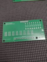
Today a bit more interesting stuff. I have created a flipper board to handle direct firing of the flippers. They will still be switches on a 5v circuit, but when on, they will operate the MOSFETs directly. As I was doing it, I also created some MOSFET boards.
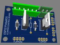
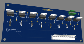
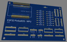
Ordered on the cheapest shipping terms, so that will be another month until I get to see what mistakes I have made.
Lots of mapping of functions in Miro and then programming in the settings to allow for web configuration of them. Boring, believe me.
Today a bit more interesting stuff. I have created a flipper board to handle direct firing of the flippers. They will still be switches on a 5v circuit, but when on, they will operate the MOSFETs directly. As I was doing it, I also created some MOSFET boards.


Ordered on the cheapest shipping terms, so that will be another month until I get to see what mistakes I have made.
Last edited:
Ashbo
Site Supporter
Crimping and soldering, was having a great time. All was well with the world, connecting up just the outhole and it fired off when it needed to....great me thinks. Connect up all the coils and we get one pop locked on and others fail to work. Seems this isn't as easy as planned (and oh how it's been planned)
Four MOSFETs blown, I must have something connected wrong or my Driver boards aren't right (more likely). If a single coil works and adding multiple doesn't I think that's where I start to redesign. It seemed too simple, it was
Back to the drawing board and read up a bit more.
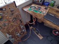
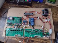
Four MOSFETs blown, I must have something connected wrong or my Driver boards aren't right (more likely). If a single coil works and adding multiple doesn't I think that's where I start to redesign. It seemed too simple, it was
Back to the drawing board and read up a bit more.


Ashbo
Site Supporter
Working theory is the boards are fine but for the lack of ground connection to the ESP32. With coils firing and only a ground to the main connection block it may have resulted in a difference in potential between the 48v and 5v circuits. If this raised the voltage seen at the gate beyond spec that could have broken the MOSFETs. Better solution long term would be to put an IC or optocoupler between the MOSFET and ESP32. Also, in hindsight, the ground trace should be broader.
Ashbo
Site Supporter
Board redesigned and ordered, stop the clock....
Ashbo
Site Supporter
Looking real good.
I really wanna do this but the coding I have not got a clue with!
The wiring, constructions, mechs, LEDs - can do that in my sleep but the code side of it scares me!
I really wanna do this but the coding I have not got a clue with!
The wiring, constructions, mechs, LEDs - can do that in my sleep but the code side of it scares me!
Ashbo
Site Supporter
I
Long way to go, and every step forward currently raises more questions.
Ready for 2030 maybe
The plan is that the code side will be mostly done by the time I'm done (will take some time) with any config and customisations done in the web interface. Should then make reusing the boards and code easy for anyone.Looking real good.
I really wanna do this but the coding I have not got a clue with!
The wiring, constructions, mechs, LEDs - can do that in my sleep but the code side of it scares me!
Long way to go, and every step forward currently raises more questions.
Ready for 2030 maybe
Ashbo
Site Supporter
Back on it again this morning and testing my way through this systematically.
First test was getting the pops working. On the last iteration of the solenoid drive board, right pop fired then stayed on. The mosfet switching the coil on and off shorted so I wanted to test both pops to see what happened.
I was a bit gutted, this wasn't what I had hoped for. Right pop was fried right?.....nope, resistance of the coil checked out so it must be the mosfet....no, this tested good too.....wtf!!!?
Swapped the connections to left and right pop and the right pop worked and the left didn't...
So, out comes the logic probe and when test firing the right pop in the software, no result.
Quick swap of the 595 shift register for a new one and we are back up and running. A reassuring high "pip" from the logic probe.
So, feeling lucky, I add in another mosfet to switch a slingshot on and off and repeat the tests
That's me for today ... After the lows of a fortnight ago I will end on a high this weekend (besides, i've no mosfets left and it's payday on Monday
If at first you don't succeed....buy some more bits and slow the fcuk down next time
Ashbo
Site Supporter
Not a great deal of effort expended today. Just added some simple buttons and a wiring loom for them to connect up to the Flipper Control Board.
Worked first time, but bottled connecting the buttons direct to the ESP32, for this I'm going to use a couple of octocouplers to ensure we dont fry the CPU if a MOSFET in the future
Worked first time, but bottled connecting the buttons direct to the ESP32, for this I'm going to use a couple of octocouplers to ensure we dont fry the CPU if a MOSFET in the future
Ashbo
Site Supporter
And the inevitable lack of will power sees me chuck the playfield, PSU and boards into the game to see it in action.....
Ashbo
Site Supporter
It's been a long time since the last update because I packed it up and stored in the shed in a fit of temper and disillusionment. Convinced I didn't have it in me to make the progress I wanted, I saw (my better half convinced me) the best thing to do was take a break.
As I'm off work on my summer holiday for a couple of weeks I thought I'd resurrect the beast and see what it was that had irked me so much. Spending a day debugging my code to find out why the controller was crashing was tough, but ultimately a major mistake was found. I discovered I had created a memory leak in my code, specifically the "clever" solution I had created to display my attract mode wasn't so smart as each time it ran, the array holding the changing text slowly consumed more and more ram. Removing it restored stability to the device and order to the force so I could proceed.
I decided to simplify things and handle changing the global Strings which hold the top row and bottom row of the display within my PinballGame class instead, this now keeps the game code within the class and I'm not chasing around trying to catch state changes throughout my code. Such a change I would have strongly resisted a few months ago as a backward step and stubbornly tried to fix the unfix-able. My beautiful wife was right again - sometimes you need to put down the toys and focus on real life for a bit.
I have since been fiddling around with the sound and agree with Alan (https://www.pinballinfo.com/communi...et’s-make-a-pinball-machine.50005/post-427070) these boards are amazing. I'm planning on getting a chime unit (I love them) to use in the machine, so every sound is currently a chime.
EDIT: forgot, also started on code for scores. This should allow for scores for switches to be edited in the GUI, and hopefully, modes to be created in the GUI. I am now conscious of over egging the GUI, rules will be much easier in the source code than within the GUI.
Last edited:
Ashbo
Site Supporter
Hello bud.
WHEN I eventually do mine I was going to use some PCBs I found on amazon where the solenoids like the two slingshots, the pop bumbers would not be driven via the CPU directly - like special solenoids on system 11. These boards after a switch has triggered fire one or two relays (one relay to go to the coil, one to go off to the CPU to add points....)
Within the software on these boards you can program it so when the switch is pressed it will only trigger for 'x' milliseconds - and not trigger again until the switch was deactivated. Thus not blowing coils.
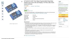
Annoying thing there is no instructions when you get the PCB so you have to work it out for yourself.
Anyway - watching with interest @Ashbo as ever.
WHEN I eventually do mine I was going to use some PCBs I found on amazon where the solenoids like the two slingshots, the pop bumbers would not be driven via the CPU directly - like special solenoids on system 11. These boards after a switch has triggered fire one or two relays (one relay to go to the coil, one to go off to the CPU to add points....)
Within the software on these boards you can program it so when the switch is pressed it will only trigger for 'x' milliseconds - and not trigger again until the switch was deactivated. Thus not blowing coils.

Annoying thing there is no instructions when you get the PCB so you have to work it out for yourself.
Anyway - watching with interest @Ashbo as ever.
Ashbo
Site Supporter
Woweee these exist!? That's incredible  I wish I had discovered these before spending days writing glitchy code. I must try these, thanks so much
Edit: and the shameful amounts of mosfets I have already blown
Edit2: sweet ....https://amzn.eu/d/05qrsA22
Edit: and the shameful amounts of mosfets I have already blown
Edit2: sweet ....https://amzn.eu/d/05qrsA22
Last edited:
an issue with those boards is that you have to set the timings up on the board itself. So if you need to replace one, make sure you’ve documented the settings, so whoever is installing the replacement, has instructions on how to
Ashbo
Site Supporter
Spent the weekend in Budapest which was awesome and had a nice surprise when I arrived home. The shaker motor had arrived.
I don't have a 12v supply to test it with, but I do have some old PC PSUs in the shed, so butchered one to give me some more power options in the cab.
The video is proof that it works. Result!
The plan is to operate this using a relay which I have 3 free on my board at the moment.
There is a capacitor that has been cut which is placed between the poles of the motor, I will replace soon.
Ashbo
Site Supporter
Strapped the motor into the machine. It's intense. Looking forward to controlling the power by rapidly turning the relay on and off.
You’ll burn the relay contacts out. Why not a mosfet ?
Ashbo
Site Supporter
Poor design choices
 , I have spare mosfet capacity too. I was concerned about the motor spilling voltage back at the Mosfet and killing it.
I have been reading up on shakers here : http://mjrnet.org/pinscape/BuildGuideV2/BuildGuide.php?sid=shakers
Looks like I need a diode and some chokes to protect the components connected to the motor. Honestly a new concept on me (since A Level physics in 1997), so just messing about at the moment.
Didn't think about the mechanical wear on the relay, but of course it's likey to manifest if using the relay to pulse the voltage.
Cheers mate, good call

Bad ideasYou’ll burn the relay contacts out. Why not a mosfet ?
I have been reading up on shakers here : http://mjrnet.org/pinscape/BuildGuideV2/BuildGuide.php?sid=shakers
Looks like I need a diode and some chokes to protect the components connected to the motor. Honestly a new concept on me (since A Level physics in 1997), so just messing about at the moment.
Didn't think about the mechanical wear on the relay, but of course it's likey to manifest if using the relay to pulse the voltage.
Cheers mate, good call
You'll get back EMF from the motor. This is why all the shakers I supplied had a diode.I was concerned about the motor spilling voltage back at the Mosfet and killing it.
Ashbo
Site Supporter
Cheers Phil.You'll get back EMF from the motor. This is why all the shakers I supplied had a diode.
Ashbo
Site Supporter
Following a inspirational trip to Budapest, with all the pins on offer, I fell in love with a coffee table...trust me. So decided to have a go at making one that plays.

A few hours head scratching, Fusion360 testing and internet scouring, I decided to have a go. I have most of what I need already!!??
Off to B and Q, cutting list in hand...

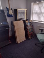
I should really be making a nice mitre joint, but I don't have the space, so made some 3d printed bits to hold the sides flush and a 3d printed thing to help me mark up the centre points to drill for screws and dowels.
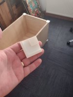
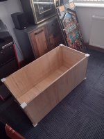
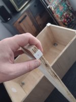
After an afternoon of huffing and puffing, I was amazed to see my measurements were just about ok.
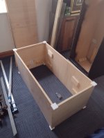
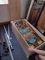
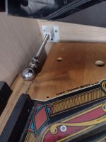
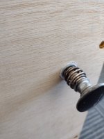
Some more 3d printing to get a shooter housing that angled up 6 degrees to meet the playfield. I used a bolt and a few nuts to check my measurements before drilling.
Also got some Bally Chimes. Will update when these are in, but I have cleaned, wired up and manually tested them.
View attachment VID-20240811-WA0003.mp4

A few hours head scratching, Fusion360 testing and internet scouring, I decided to have a go. I have most of what I need already!!??
Off to B and Q, cutting list in hand...


I should really be making a nice mitre joint, but I don't have the space, so made some 3d printed bits to hold the sides flush and a 3d printed thing to help me mark up the centre points to drill for screws and dowels.


After an afternoon of huffing and puffing, I was amazed to see my measurements were just about ok.


Some more 3d printing to get a shooter housing that angled up 6 degrees to meet the playfield. I used a bolt and a few nuts to check my measurements before drilling.


Also got some Bally Chimes. Will update when these are in, but I have cleaned, wired up and manually tested them.
View attachment VID-20240811-WA0003.mp4
Loving the coffee table. I am going to have one to make one myself after someone sniped the backbox on ebay that belonged to the bottom of a game I already had
Ashbo
Site Supporter
eBay creates hope, then ruins your dreams.Loving the coffee table. I am going to have one to make one myself after someone sniped the backbox on ebay that belonged to the bottom of a game I already had
I'd love to know who and why paid so much for half of a Ten Star that I own the other half ofeBay creates hope, then ruins your dreams.

