What's new
Pinball info

Register a free account today to become a member! Once signed in, you'll be able to participate on this site by adding your own topics and posts, as well as connect with other members through your own private inbox!

In Progress Mishmash Homebrew - Pt II - Playable Coffee Table

Quick update - having a few days with normal life usually helps and this time it's no different. I have been reading up around how the ESP32 works and it seems I have been setting my tasks (which I pin to cores) with too high a priority. The more I pin at a high priority the less stable the ESP32 will become. There are many internal processes that need to take place to keep the system on a chip running and if I am too agressive with my code it all breaks down. This is what I saw with my LED corruption. I have since made a table of what's running on each core so I can visualise what is going on and this helps me to ensure higher priority tasks keep running (Pinball stuff) and lower priority tasks need to wait (Web server).

1728118931847.webp

So first test this morning and no LED corruption. I'll likely have some undesirable impact on the pinball game (always a sceptic) but at least I can start to plan how I will manage to prioritise resources on this awesome little chip.
 
A day of highs and lows. High point was getting some functions set up to do a basic chase, all on all off and odds and evens given an array of LEDs


The low was plugging my dev board into the wrong sockets and mincing it with. That's another £6.99 wasted 😂😂😜
 
Picked up an old oak TV table that I plan to repurpose/salvage the wood from to make the surround .... May need to see if I can get some help from my dad (as is the way 😁)

IMG_20241013_142952707_HDR.webp
IMG_20241013_152058826_HDR.webp
IMG_20241013_152929149_HDR.webp
IMG_20241013_152933520_HDR.webp
 
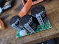
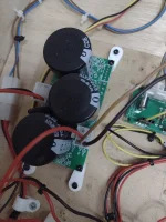
Plucked up the courage to assemble and test the power filter board. (OPP Project - https://pinballmakers.com/wiki/index.php?title=OPP#Hardware)

IMG_20241027_121508943_HDR.webp

The theory here is the bulk capacitors will hold enough charge to fire coils without stressing the 48v switched power supply.

It was very scary firing this up for the first time. One thing wrong and that's potentially an expensive repair bill.

As it happens it went to plan, however I need to change where this sits in the design as currently it's wired up after the 48v relay I have, this means it can provide its residual capacity to coils even after the relay is deactivated. Not ideal. I also need to find some way of safely discharging the caps as they have a dangerous level of charge in storage when off.

 
Last edited:
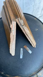
I've been relying on my favourite (and only ;)) dad to help with (do all of) the work in cutting down the oak TV stand so it will become the coffee table top for this project.

IMG-20241027-WA0000.webp

Some interesting structural features to navigate, but I have been assured all will be well 🙏
 
Rewired the 48v so the power filter board sits between the 48v rail and the PSU the PSU goes to fuse, then relay, the power filter then a feed to 48v rail and a feed to the play field coils. This stops coils firing on startup when the relay is off.

We do still store 48v in the caps on power off, I need to put in a bleeder resistor. This could be a 5W 10k resistor across the caps, but it's more likely a 10ohm 20W resistor across the caps but switched on only when the power is off.

I have been playing with creating some tunes on the chimes and testing flippers. The EOS switch on the upper right flipper is a bit old and will need a replacement . This wasnt working as expected so adjusted when I checked the coil as it was getting a bit hot.

A bit of a visual of the flippers. It's nice the PSU isn't cutting out now.

 
We do still store 48v in the caps on power off, I need to put in a bleeder resistor. This could be a 5W 10k resistor across the caps, but it's more likely a 10ohm 20W resistor across the caps but switched on only when the power is off.

A 10ohm resistor would be seeing 230watts being dissipated across it, so don't do that 🤣

A 10k 1/2watt resistor in parallel with the capacitor would be fine (the actual power is about a quarter watt at 10k) You could also add a power LED in parallel as well, so you will have a visual indication of the charge state as well as speeding the discharge slightly
Nice one @lukewells. I think I'll give that a go, assume a suitable resistor in front of the led to prevent further destruction 💥💥💥😜
 
Nice one @lukewells. I think I'll give that a go, assume a suitable resistor in front of the led to prevent further destruction 💥💥💥😜
A 4.7k resistor would give you 10ma into an average red led, but it would be dissipating near 1/2 watt

I would suggest you can improve the situation by using a blue LED as they tend to have a higher forward voltage, so will put less strain on your resistor. a 1watt would be better, but a 1/2watt is probably fine.

Also now that I calculated the power at the resistor, the LED and its resistor would actually run down the caps in a reasonable time alone. Adding a second dedicated bleed resistor in parallel would not be strictly required, but hey resistors are cheap and it would just make it faster.

Hope that made sense? (so 4.7k res + LED in series, placed parallel to the caps, then optionally another 10k resistor (also in parallel to the caps))
Perfect sense sir. Thanks for the explanation. I think this may be achievable onboard the opp circuit board, but will do it parallel from the outputs ( I have one pair spare) top and bottom right most on the output connector. Top positive and bottom ground.


17301347186714870424792056310745.webp
 
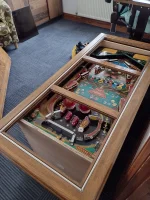
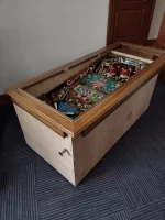
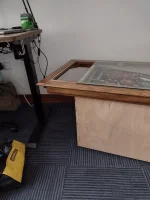
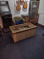
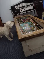
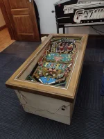
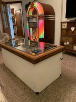
A monumental effort from my brilliant dad means I can now order some glass...
IMG_20241106_173923689_HDR.webp

IMG_20241106_173620073_HDR.webp

IMG_20241106_173602645_HDR.webp

...it was a tough job with steel fillets reinforcing the original mitre joints. These needed to be removed and hardwood fillets being used once cut down. The side strips were also never level and corners that were once legs were cut down, glued and screwed.

Not a bad result for a £20 upcycle project.

The glass (10mm thick toughened glass with beveled and polished edges) will be considerably more expensive.
 
Today I faced a choice between Christmas shopping and messing about with the coffee table. Coffee table won so I took to getting some jobs done I have been putting off.

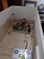
First, thanks to @lukewells for the advice, I wired in a 10K 5W resistor as well as an LED and a 4.7k resistor in series with a blue LED (these both in parallel) which works nicely as a bleeder for the capacitors. It seems after a couple of minutes the high voltage stored is down to around 5v or less.

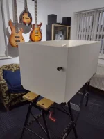
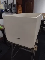
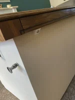
Second, I wired in some unconventional chrome buttons. These are much smaller than the usual pinball buttons, but I wanted to maintain the illusion it was still furniture first - game second.

IMG_4636.webp

Finally, a few tweaks to the code that were needed to get a game going.

A long way to go but better....

 
Last edited:
This forum is brilliant. I realised the power surge when running both right flippers is triggering my switch matrix. You see it in the video when the chimes fire when firing the flippers (I have code to ring on every point scoring) and also random fire of pops and slings.

Thanks to google, straight back to the forum…


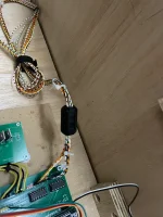
Ferrite choke it is….
 
If your ferrite has not yet arrived, you can test out the theory by wrapping some tinfoil around the switch part of the loom that is causing your problem and then ground it and see if the situation is resolved/improved
 
Or a 10k-20k resistor to pull up/down the signal at the problematic switch
Agreed. I think you had one on the right flipper button originally. I never really understood theory but do now. Should definitely sort it.

My first fear was somehow the upper flipper having 48v earthing to multiple coils, but that’s not possible. All mosfets in tact so must be EMF.

A long hold on the flipper caused the psu to overload and cut out, but that’s was 6 coils continuously firing.

Another simple test will be disable auto fire on the coils and I should be back to flippers only. If not it’s a wiring issue.
 
If your ferrite has not yet arrived, you can test out the theory by wrapping some tinfoil around the switch part of the loom that is causing your problem and then ground it and see if the situation is resolved/improved
A venture into the loft and I have found one. I knew that random box of sh!t would come in handy 😎
 
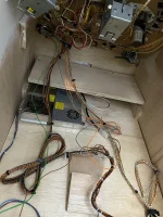
Ferrite made a small improvement. Separating low voltage and high voltage looms also improved things. Still some phantom fires of switches. Will look to see if I can do anything in code as well as earthing and further insulation

IMG_4638.webpIMG_4639.webpIMG_4640.webp
 
Separating high and low voltage cables in the lower part playfield did the trick. A bit of foil around the low voltage cables where they get within a cm of high voltage cables for good measure.

Upper flipper also weak and pointless, needs a rebuild but as it’s my machine, my rules, I have removed for now.

Had a few games and it feels more balanced.

IMG_4641.webp
 
Last edited:
I was asked on YouTube to explain a bit more of how this is working at the moment. I realise I can’t say MOSFET properly as well as calling a rail a relay. It’s lunchtime and I have to get back to work soon so this first take will be the last 🤣🤣

 
@Ashbo what an amazing journey.

I've just read start to finish, not sure how I've not seen this thread before. You're building on a great basis to get things moving but also made a lot of this your own.

I'm just a bit disappointed not to see the topper in the coffee table, I hope it's been kept as a display item.
Aw thanks @Goodwinsplace.

Unfortunately the topper is no more. All dreams of a tether have been dashed 🤣🤣

I played the game properly at the weekend and was extremely disappointed in just how dull it was!! I will finish this so it’s all working as it should, however my next homebrew will have at least one ramp 🤣
I'm sure it's great. And the amount of knowledge you've developed is amazing.

If you do want to try and OPP setup next I have some spare PCBs I can send over.
 
Back
Top Bottom