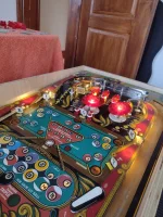
someone hoping you want it bad, possibly ?I'd love to know who and why paid so much for half of a Ten Star that I own the other half of
Pinball info
You are using an out of date browser. It may not display this or other websites correctly.
You should upgrade or use an alternative browser.
You should upgrade or use an alternative browser.
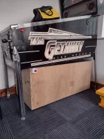
In Progress Mishmash Homebrew - Pt II - Playable Coffee Table
- Thread starter Ashbo
- Start date
Well jokes on them then as I am going to make it into an active coffee table inspired by yours :
Ashbo
Site Supporter
Boring update.
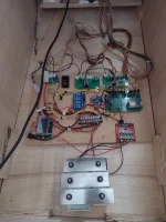
Going to need to make a power filter board as I now have the playfield at an honest 6.5 degrees which shows the 24v power supply dropping out on the outhole and flippers.
I plan to take advantage of the power filter board here:
 pinballmakers.com
I may need to upgrade to a 48v PSU but I'll hold off until it's all built. 24v is fine for testing and perfect for my chimes.
The ATX PSU is mounted now and that gives me 12v for the shaker motor.
A 2004A LCD display came today which will offer a small makeshift score display mounter above the playfield apron for the time being.
Going to need to make a power filter board as I now have the playfield at an honest 6.5 degrees which shows the 24v power supply dropping out on the outhole and flippers.
I plan to take advantage of the power filter board here:
OPP - Pinball Makers
I may need to upgrade to a 48v PSU but I'll hold off until it's all built. 24v is fine for testing and perfect for my chimes.
The ATX PSU is mounted now and that gives me 12v for the shaker motor.
A 2004A LCD display came today which will offer a small makeshift score display mounter above the playfield apron for the time being.
Ashbo
Site Supporter
Ashbo
Site Supporter
.
Last edited:
Ashbo
Site Supporter
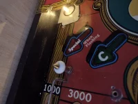
As there is a lot of cosmetic work to do on the body, but I still want to work on the game I have been struggling with how to connect the cabinet buttons.
The wrong hole in the wrong place could make things tricky later on.
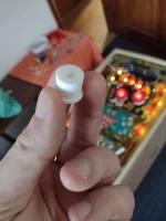
For now, a few 3d printed button holders with Sawna type 30mm buttons should do the trick.
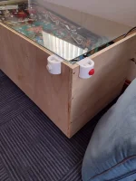
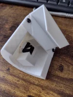
The wrong hole in the wrong place could make things tricky later on.
For now, a few 3d printed button holders with Sawna type 30mm buttons should do the trick.


Ashbo
Site Supporter
Ashbo
Site Supporter
48v PSU arrived today. Tried for a few mins this evening. Wow, what a difference!!!
Unfortunately the flipper board I made was the same batch as the solenoid boards I made and found were useless. The issue was I failed to make the earth trace big enough to handle the load. Smoke stopped play


Time to get editing and ordering from jlcpcb.
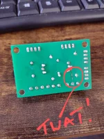
Unfortunately the flipper board I made was the same batch as the solenoid boards I made and found were useless. The issue was I failed to make the earth trace big enough to handle the load. Smoke stopped play
Time to get editing and ordering from jlcpcb.

Ah fuseable traces48v PSU arrived today. Tried for a few mins this evening. Wow, what a difference!!!
Unfortunately the flipper board I made was the same batch as the solenoid boards I made and found were useless. The issue was I failed to make the earth trace big enough to handle the load. Smoke stopped play
Time to get editing and ordering from jlcpcb.
View attachment 259178
It's only a protptype, just solder some wire across the back of the board on the current carrying traces so you can carry on testing
Just get some solid cable and bridge it !
Easy !
Easy !
Ashbo
Site Supporter
The latest flipper board design was delivered today. It would be rude not to give it a go.
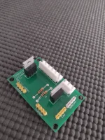
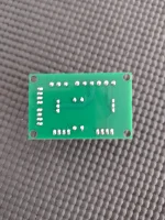
First attempt ended in a blown MOSFET and some head scratching. It seems the higher voltage was arcing to connectors I wasn't expecting. Added some insulation and that solved that
The power from the new Meanwell 48v 350W PSU is impressive.


First attempt ended in a blown MOSFET and some head scratching. It seems the higher voltage was arcing to connectors I wasn't expecting. Added some insulation and that solved that
The power from the new Meanwell 48v 350W PSU is impressive.
Ashbo
Site Supporter
Dull update. I was measuring voltage out of the PSU (after adjusting output from 48v to 43v ) whilst operating the flippers and was concerned that there was no voltage drop seen when multiple playfield coils were fired and none for the left flipper, but when the right flipper was actuated the drop was clearly visible on a multimeter. I looked like 10v drip for a half second press. Pushing my luck I held the right button in and after a second or so the PSU shut off.
It didn't come back on a concerned few moments passed. Had I blown my MOFSETs again??
Turning of the mains for a minute and then turning back on again and we were back in business.
I was able to hold the left flipper for ever with no voltage drop and a quick tap on the right saw a drop again. A hold, and off goes the PSU. There must be a short somewhere causing the PSU to cut out. I remember in Alan's blog he even had to change the eos switch because his 44v PSU kept quitting. Same fault different error this time, eos switches are perfect.
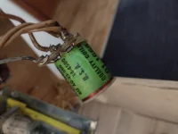
I've had a look at the coils and it seems we have less that 2 ohms on both windings on the upper flipper which surely isn't right. It's much less that the other coils (off the top of my head about 80 and 4 ish).
A couple of replacements ordered off eBay. Why is every pin a money pit???

You could put in modern flipper mechs and use two mosfet outs - one for hold and one for the kick. Then a low voltage EOS would need to be used.
I also see a lot of people use the wrong EOS switches.
I also see a lot of people use the wrong EOS switches.
Ashbo
Site Supporter
Thanks mateYou could put in modern flipper mechs and use two mosfet outs - one for hold and one for the kick. Then a low voltage EOS would need to be used.
I also see a lot of people use the wrong EOS switches.
Deffo could be a way to go. A small microprocessor controlling an initial full power bust to the flipper using a MOSFET then moving to PWM for the hold. Would make things much simpler and safer.
My initial concerns were doing this through the esp32, we are taking up GPIO pins which can be ill afforded to be given up. But a simple esp8266 could handle this on a stand alone flipper board. It could even send out flipper button events to the esp32 via dedicated io, or serial or even WiFi (perhaps too much latency).
Just add some 595 Shift registers to expand your gpio pins - or a dedicated SPI i/o expander like the MCP23016
Personally I've always used the shift registers cost they are cheap and easy to use. I will get round to using an MCP23016 or similar at some stage in the future though, just for the hell of it.
Personally I've always used the shift registers cost they are cheap and easy to use. I will get round to using an MCP23016 or similar at some stage in the future though, just for the hell of it.
Ashbo
Site Supporter
Did think about the shift, however (in my head) getting around coding the PWM control seemed overkill when a dedicated pin could bo it natively.Just add some 595 Shift registers to expand your gpio pins - or a dedicated SPI i/o expander like the MCP23016
Personally I've always used the shift registers cost they are cheap and easy to use. I will get round to using an MCP23016 or similar at some stage in the future though, just for the hell of it.
All academic at the moment because I'm not investing in any new flipper mechs any time soon, unless I win the pools
It's good theory though, for a much more reliable pinball experience
Yes, agree I'd always use a dedicated pin for PWM, and all other I/O can go via the Shift Registers / I/O expanders.Did think about the shift, however (in my head) getting around coding the PWM control seemed overkill when a dedicated pin could bo it natively.
All academic at the moment because I'm not investing in any new flipper mechs any time soon, unless I win the pools
It's good theory though, for a much more reliable pinball experience
Ashbo
Site Supporter
So a quick tea break late morning on Friday I had an idea. Let's see how this mlyar comes off the old playfield. Within minutes it was gone, literally just lifted straight off. That was lucky I thought. Hmmm, not so.
During testing I was often distracted by what I thought were lose connections or arcing under the playfield. It seems it was the crackling of old mylar bubbled up over dropped inserts.
Back to the tale of misery, here is the glue from the mylar proudly shining out.
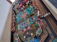
So fast forward to Friday evening and realising I was in doo doo as the goo gone didn't shift this sticky covering at all. The only thing that would cut the mustard was isopropyl, flour and the skin off my fingers.
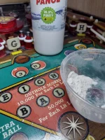
When rubbing dry flour over the playfield it's easy to pick out the glue spots
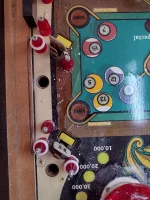
No word of a lie, this has taken over eight hours to remove the glue and I've got flour everywhere.
A quick coat of wax this evening and all is forgiven. This playfield is planking and seen better days, but she'll be right for my plans
View attachment VID_20240915_161542216.mp4
During testing I was often distracted by what I thought were lose connections or arcing under the playfield. It seems it was the crackling of old mylar bubbled up over dropped inserts.
Back to the tale of misery, here is the glue from the mylar proudly shining out.

So fast forward to Friday evening and realising I was in doo doo as the goo gone didn't shift this sticky covering at all. The only thing that would cut the mustard was isopropyl, flour and the skin off my fingers.

When rubbing dry flour over the playfield it's easy to pick out the glue spots

No word of a lie, this has taken over eight hours to remove the glue and I've got flour everywhere.
A quick coat of wax this evening and all is forgiven. This playfield is planking and seen better days, but she'll be right for my plans
View attachment VID_20240915_161542216.mp4
Ashbo
Site Supporter
Guilty, doorbell machines. You bells are not that ear piercing though.God I love pinball chimes, but everyone else thinks it's a doorbell. Oh well
Ashbo
Site Supporter
Yesterday I began the process of installing two new ws2812b led strings having shorted the last lot by being fool hardy and careless.
Painstakingly used a staple gun to line up each led with each insert and document the led number in the chain against the insert name.
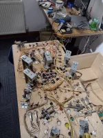
Once that was done I used pvc tape to cover the underside of each led element to ensure that I had some protection from making the same mistake twice.
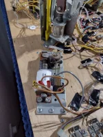
This evening I set about reinstalling the right flipper coil and the new upper flipper coil. I used some shrink tubing to cover the exposed contacts to keep things clean and tidy.
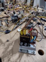
One final job was to add a connection block to handle the 5v, ground and data lines needed for all gi and insert lighting
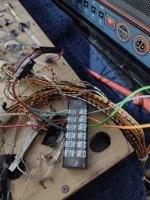
It's not pretty, but hopefully she will work.
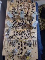
Painstakingly used a staple gun to line up each led with each insert and document the led number in the chain against the insert name.

Once that was done I used pvc tape to cover the underside of each led element to ensure that I had some protection from making the same mistake twice.
This evening I set about reinstalling the right flipper coil and the new upper flipper coil. I used some shrink tubing to cover the exposed contacts to keep things clean and tidy.


One final job was to add a connection block to handle the 5v, ground and data lines needed for all gi and insert lighting

It's not pretty, but hopefully she will work.

Ashbo
Site Supporter
It's been a weekend dominated by LEDs. My word these can be fun, they can also drive a man to drink!!
So managed to get the GUI to affect the live states of the LEDs. This is useful so I can verify the id I have documented for each LED is actually correct. It may also help later on being able to programmatically get an LED name and location. I plan to add a playfield coordinate for each LED so this can help in creating nice attract mode displays.
I also worked on the led class in the code, giving it mechanisms to "tick" and change state from on to off for flashes.
I encountered a big problem on the long length of LEDs in the playfield where random corruption would occur. Thinking this could be signal degradation of the data line, I purchased a logic level shifter from Amazon to boost the signal from 3.3v to 5v. This didn't work and I was left scratching my head and Googling like mad.
I think I have cracked it, when the LED libraries (FastLED and Adafruit_Neopixel) run on the same core as an interrupt (or WiFi) is running, it seems to cause the show methods of the LED to cr@p out intermittently. I hope I have found the fix which would be to run the LEDs on core 0. Seems to work on my test setup, so fingers crossed.
Ashbo
Site Supporter
There is still time, that's my kind of price pointShould of used these for GI's mate.
We used these on the prototype Heighway of Full Throttle.
You can get them 5v or 12v.
Use them a lot in jukeboxes too.
View attachment 262427
You can have mine if you like as I won't be using them, I bought some to test on the P-ROC PD-LEDS but I don't think they will get used. My GI are RGB so I don't think I need any serial.
No worries take them off my hands, send address and I'll ship tomorrow.Wow there is an offer, thanks @dave
I have fastled running on same core as wifi. No issues.
You may need to inject 5v 1/2 way down your string of LEDs.
You may need to inject 5v 1/2 way down your string of LEDs.
Ashbo
Site Supporter
I'm seeing behaviour like this.I have fastled running on same core as wifi. No issues.
You may need to inject 5v 1/2 way down your string of LEDs.
ESP32: timing error every 1ms corrupts LED pixel data · Issue #139 · adafruit/Adafruit_NeoPixel
On the ESP32, an extra delay of about 5 microseconds is inserted into the signal output every millisecond. This is far outside the Neopixel timing tolerance of 150 ns, so it leads to incorrect valu...
An old bug, but ive got timers going and WiFi, and web server and processing routines all running at the same time. I need to test more, but I can replicate on 12 LEDs now so it's not my original thoughts, power, then logic level. I'm not good enough to understand why it's broke, but if I isolate LEDs on core 0, it seems to be resolved

