What's new
Pinball info

Register a free account today to become a member! Once signed in, you'll be able to participate on this site by adding your own topics and posts, as well as connect with other members through your own private inbox!

In Progress Hook, line and sinkered...

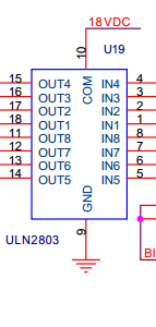
That seems unfortunate, what pins do you think you shorted between? Is pin 13 shorted to ground when neither the lamp row or column to the playfield are plugged into the board?

Yea I'd socket every chip you ever replace so you don't have to solder again if it ever goes wrong. Unfortunately not all components are born equal, there can be fakes around on eBay. Where possible I tend to buy bits from Farnells, Pinball Mania and such like. The trouble with Farnells is you have to spend a minimum of £20 a time unless you have an account. Those bits on eBay are so cheap for so many I'd go for it. Everybody seems to have a different idea on what sockets they prefer, personally I'd go for the "precision/turned" variety in that listing.

Have you decided where you are going to source the IRL540Ns? Power Transistors in particular you want to get good quality ones as they are more stressed than the chips.
 
It's kind of hard to t/shoot now what with the fuse blowing and cutting off the 18V to the board. What I have done is unplug CN6 and CN7 then DMM diode test with Red probe on Pin 9 ground (per Clays guide) most of the input/output pins test at approx 0.6V but pins 11 and 12 are below 0.05V. Pin 11 o/p leads to the column driver of the column I first noticed out.

These IRL540N on eBay are just too cheap - http://www.ebay.co.uk/itm/200925501400

I've dropped Jim @ Rottondog a note, I read on Pinside that they go above and beyond for service! They rock! , so who knows they might help out if the problem was obviously at manufacturing.

upload_2015-4-6_14-49-28.png
 
Yes. Just need an 18 pin socket. I always go for the standard ones, I never liked those precision ones - they actually seem less precise in the way they grip the pins.
 
Yea or you can get really long sip strips and then cut them down to length which means you don't have to stock every size. Another nice touch using these is they don't cover up as much of the board so you can see traces that run under the chips. Its also easier to see if a solder has run all the way through a joint to the top side.

Here's an example of what I'm on about: http://m.ebay.co.uk/itm/281474772241?nav=SEARCH
 
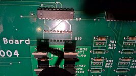
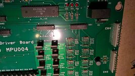
Started prepping the MPU for the new components last night. Need to remove Q72-79 which are the wrong component - note all TIP107's. Also U19 which I've damaged whilst diagnosing.

WP_20150407_18_07_25_Pro.jpg

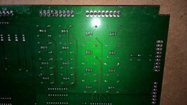
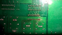
the original tidy work on underside
WP_20150407_18_08_26_Pro.jpg

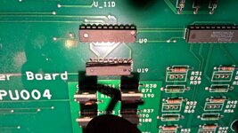
Dremel'ed off U19 using a cutting disk and steady hand
WP_20150407_19_49_40_Pro.jpg
WP_20150407_19_50_00_Pro.jpg

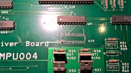
All gone, unfortunately my solder pump broke so I couldn't clear the U19 holes completely.
WP_20150407_20_07_59_Pro.jpg

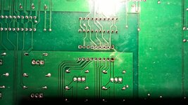
the underneath
WP_20150407_20_08_40_Pro.jpg

initial continuity testing is good but I'll double check once I complete de-soldering before re-assembly
 
Nice work, @astty. Slow and steady wins the day when doing circuit board repairs! Strange about those TIP107s being wrong in Q72-79. I'm no expert but pretty sure that a PNP Darlington isn't a suitable replacement for an N-channel MOSFET.
 
Nice work, @astty. Slow and steady wins the day when doing circuit board repairs! Strange about those TIP107s being wrong in Q72-79. I'm no expert but pretty sure that a PNP Darlington isn't a suitable replacement for an N-channel MOSFET.

Even Rottendog's own circuit diagram state 20N10L transistors for Q72-79

Yes, it was a real b*gger to diagnose, as you don't expect to encounter this with the assumption it was working before, just a rare fluke I guess that explains why I couldn't find any instance of a similar problem on the net - all CPU lights OUT Yes Lots of info, ON - NO!

I've exchanged emails with Jim Knight @ Rottondog, who confirms the boards are tested by the board house and him before shipping but this was sold 6 years ago.

If the upgraded replacements I've ordered fix it then I'm happy.
 
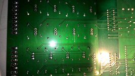
I carried on the de-solder of the MPU today and its not going as well as I'd like with some damage on the through hole plating around IC U19 - pin 10 is in bad shape on both sides, and pin 9 damaged underneath. There is still connectivity to the exposed traces which I should pickup with careful soldering. I bought some dual-wipe sockets for this job - but now I'm thinking I need the SIL strips so I can better access both sides and test the connectivity. @Nedreud you logged similar work on your Gold Ball - when you soldered the topside of the SIL strips did you apply the iron to the underneath? (I know the theory is it should all flow through from the underneath which I'll try and test first).

Am leaving for SWL Pin Golf shortly so hopefully can pick some brains there on this too.

WP_20150411_08_26_59_Pro.jpg

WP_20150411_10_51_36_Pro__highres.jpg
 
Ive yet to see a Pinball board, old or new, where you don't loose at loose one Through plated hole. More than likely just me tho, but i do get it nice and hot, so no reason for it not to come out properly!
 
Just give those pads and tracks a good clean up afterwards. I've had and seen far worse, especially after battery corrosion damage which just eats straight through the fine tracks for 5V logic signals. An excellent tool to have is a fibreglass pencil:

http://www.maplin.co.uk/p/abrasive-fibreglass-pencil-kr61r
abrasive-fibreglass-pencil[1].jpg

Buy them somewhere else though - £7.50 at Maplin is too expensive.

The pins on your socket will take care of the through-hole connection, so don't worry about that. If the pad falls off then solder the pin in place on the other side as best you can then scrape off the green lacquer along the connecting track and use a very thin piece of nickel-plated wire to complete the circuit (or at a push snip a leg off a resistor).
 
I decided to tackle the 'prepared' MPU last night, to get my CPU controlled lights working.

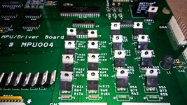
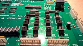
First installed Q72-79 with upgraded IRL540N - they are specced as 20N10L on the schematic but 13N10L is actually used throughout the Rottondog board for these. The board came to me with incorrect TIP107's fitted here which are correctly used for the bank of lamp column drivers to the side which are the same casing so easy confused (at manufacture?)

WP_20150415_19_53_54_Pro.jpg

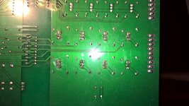
The underneath, not the tidiest I was using new 60/40 Rosin core for the job.
WP_20150415_19_56_04_Pro.jpg

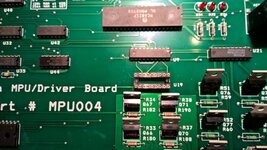
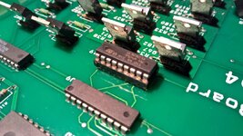
They were ok to fit (24 solder points) so I decided to continue fitting U19 the ULN2803 I shorted with the logic probe. My SIL strips hadn't arrived but I had an 18 pin socket I initially bought for this.
WP_20150415_19_53_40_Pro.jpg
not the tidiest underneath, it did clean up a bit using a fibreglass pencil. Not sure what I did wrong here - perhaps not burn the flux off enough. I'd melted the previous socket so was wary on heat application.
WP_20150415_19_55_42_Pro.jpg

new IC snapped in position
WP_20150415_20_00_50_Pro.jpg

As I'd taken hi-res photos of the traces above /below U19 (highly recommended particularly if covering with a socket) I was then able to check continuity between and from all pins to their destinations on both sides of the board. Where I'd lost one of the through plated holes I had to dab a little solder on the topside to pickup the trace.

Then MPU back into the machine. Good start the 8A fuse didn't blow and after boot here's a short video of the result - I have working HOOK lamps at last!!!
http://1drv.ms/1ayQyww

One major known problem remaining, I'm missing some voice sounds and Voice ROM2 isn't testing in diagnostics, I have a replacement on order to try.
 
Nice work, @astyy! You must be well happy with that :D

Soldering looks good to me. Reworked pads will never look as good as the originals, it's just not the same process. Commercial boards get washed and scrubbed before and after, and are most likely soldered by floating on a pool of solder. Different scale. But your work looks clean and tidy, and you've not overdone the amount of solder.
 
Then MPU back into the machine. Good start the 8A fuse didn't blow and after boot here's a short video of the result - I have working HOOK lamps at last!!!
http://1drv.ms/1ayQyww
.

Im pretty sure I had that allright when i had it going. I also had the voice. had loads of I hate, I hate peter pan. Bangerang etc... I guess storage hasnt been kind to it, should have known something wasnt quite right when it was popping fuses.

Seems it didnt just need a fuse :p
 
I also had the voice. had loads of I hate, I hate peter pan. Bangerang etc..

Yes, I get those voices, they're probably from Voice ROM1 which tests ok, but Voice ROM2 doesn't test ok and I understand it should say something when the game boots and when a game starts which it doesn't.

So far, I haven't spent much on major items. just my time and expertise (cough!)
 
pretty sure it says i hate i hate peter pan on start up ?? and a crowd shouts HOOK or something similar a few times


----------
edit:

ok it seems to just say hook a few times

 
Last edited:
pretty sure it says i hate i hate peter pan on start up ?? and a crowd shouts HOOK or something similar a few times


----------
edit:

ok it seems to just say hook a few times


Depends what version code you're running. I just updated mine and a few things have changed.
 
@PeteB what version have you loaded? Mine says

Display 4.0.1
USA 4.0.8

I don't hear any noise on startup but after about 30s 'i hate Peter Pan' when Hook scrolls up the display - but Voice ROM2 is failing in Diagnostics so I must be missing something.
 
I'm still working on getting it all playing properly not too much to go now - voice sounds and some general maintenance to the pops.

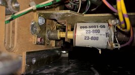
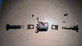
I noticed the fibre yolks are broken on two of the pop bumpers. This one has a damaged coil too (its the VUK and caught the rails lifting the pf) also note two diodes!

WP_20150426_11_03_08_Pro.jpg

That is one bust yolk
WP_20150429_18_23_27_Pro.jpg

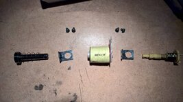
The bits all look a bit mucky - I can live with it
WP_20150426_12_31_49_Pro.jpg
No I cant - damn you @Nedreud and @PeteB and and the rest of you for setting high standards :)
WP_20150428_19_33_09_Pro.jpg

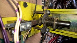
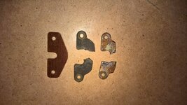
On to re-assembly, oops there's a metal yolk too and that's bust and I didn't order replacements for those
WP_20150429_18_33_14_Pro.jpg

You're probably all too familiar with this - tools down whilst await next order, which typically is super quick from Andy.

A quick question in the meantime - should the metal and fibre yolks be installed offset or same way round? I think the former but there are examples of each over the existing pops.
 
Crikey! Got your work cut out for you there. Good job on polishing the remaining parts haha, they're gonna work brilliantly when it's all put back together.

Yeah the pop yolks should be offset, at least on every game I've ever seen. If you look on page 38 of the manual you can just see in the diagram the straight edges overlap and the rounded/pointed edges face away. Really crappy picture but it also shows the fiber being closest to the playfield and the metal being on the bottom nearest the coil.

Did you remember to buy new spoons or are those ok?
 
Yeah the pop yolks should be offset, at least on every game I've ever seen. If you look on page 38 of the manual you can just see in the diagram the straight edges overlap and the rounded/pointed edges face away. Really crappy picture but it also shows the fiber being closest to the playfield and the metal being on the bottom nearest the coil.
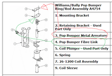
Yes you're right they do appear to be fitted in that order in the Hook manual, but mine are all fitted the other way, ie metal yolk closest to the pf then fibre closest to coil. I thought that was right as that is how it appears for a Williams pop on Andys website in this diagram.

upload_2015-4-30_15-47-38.png

Did you remember to buy new spoons or are those ok?
Spoons - No, cos I've only just heard of them from you!
 
Hi @astyy. Same on my old Ballys. The fibre yoke is closest to the coil, metal to the playfield. (I've got my GOLD BALL playfield upside at this very moment because I've just rebuilt my pops too!).

Spoons are another of those items that some like to always replace. Just make sure the inside of the cupped end is nice and smooth. Sometimes, especially if a pop bumper only has limited access on one side, the spoons can get a groove worn into them from the skirt rod which can lead to unreliable switching. The ones on all 3 of my machines have been fine.
 
Yeah your spoons might be well be just fine but looking at the rest of the assembly I assumed they would be worn. They are on the switches so easy to change later without having to take the the pop assembly out again.
 
wp_20150429_18_23_27_pro-jpg.16270


Pictures posted by 'astyy'.

Apart from the yellow colour, that could be the bumper on a 'classic' Stern such as Flight 2000 or Cheetah.

And on the V.U.K.,
wp_20150426_11_03_08_pro-jpg.16269


The coil shouldn't need two diodes fitted, whereas the replacement shown in the 'exploded' picture doesn't seem to have one at all. If there isn't one elsewhere in the driver circuit, add one across the coil terminals.
 
The coil shouldn't need two diodes fitted, whereas the replacement shown in the 'exploded' picture doesn't seem to have one at all. If there isn't one elsewhere in the driver circuit, add one across the coil terminals.
Agreed, that coil appears to have a diode pre-installed and then a second one fitted across the lugs in error. The replacement coils I've bought don't have the diodes pre-installed and I will fit '1' across the lugs. On this machine most of the coil lugs are covered in insulating tape, which I've read was DE 'factory' I will remove and check others. I have a cunning plan to use a different coloured insulation tape as I go to track my progress.
 
If you look on page 38 of the manual you can just see in the diagram the straight edges overlap and the rounded/pointed edges face away. Really crappy picture but it also shows the fiber being closest to the playfield and the metal being on the bottom nearest the coil.
I've inspected the current setup of the fibre and metal yolks and I suspect the diagram in the manual is at best not clear or worst wrong. It makes sense to me to re-install as they are. ie metal yolk facing inwards closest to the playfield and fibre facing outwards closest to the coil. ie per the Williams parts diagram above. Also have found other pictures online of DE pops installed in this way.

How are they on your Hook?
 
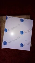
I bought a piece of 3mm clear acrylic from a company recommended by @cooldan (thank you) - cut to size and £7.10 inc. Hermes delivery. They are on eBay but you can buy direct.

WP_20150425_13_26_27_Pro.jpg

Not a brilliant pic but it looks good and now I can lock it in - I may get glass later but while working on the machine this is realy light to throw in and out.

WP_20150430_19_00_50_Pro.jpg
 
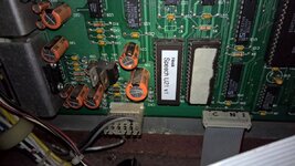
New speech ROM arrived today from @myPinballs - couldn't wait to plug it in and try it out. RESULT we have Hook, Hook, Hook on power up, more sounds and Voice ROM2 now testing ok in diagnostics. Also now get the spoken intro at the start of game which I like. This was my last unknown, electronics and mechanics wise just have to finish the pops when the metal yolks arrive and everything I know about is fixed so we're onto making it look nice.

WP_20150501_19_41_06_Pro.jpg
 
Back
Top Bottom