Pinball info
You are using an out of date browser. It may not display this or other websites correctly.
You should upgrade or use an alternative browser.
You should upgrade or use an alternative browser.
All sorts of Clocks!!
- Thread starter AlanJ
- Start date
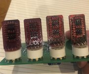
Waiting for the nixie clock next
i am going to do a led nixie clock soon
Sent from my iPhone using Tapatalk
There are tons of folk doing nixie tube and vfds, so i fancy doing something different. but....i do have a few numatron tubes. enough for 2 or 3 clocks. just need more hours in a day.
Sent from my iPhone using Tapatalk
Sent from my iPhone using Tapatalk
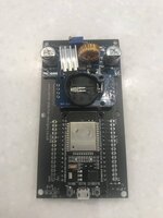
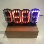
Also made up a funky clock using the above board and some APA106 Addressable LEDS that I've put on 'plug in 7 segment' boards:
The clock can show time, date, day, month, year, seconds in a variety of colour patterns and can also show colourful display patterns. All configurable via Wi-fi.
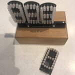
I seem to be spending more time designing and making clocks than playing pinball !!!
The clock can show time, date, day, month, year, seconds in a variety of colour patterns and can also show colourful display patterns. All configurable via Wi-fi.


I seem to be spending more time designing and making clocks than playing pinball !!!
I think you have a clock problem
Pretty sure there's a blue pill that can help with that

Morpheus offered me a choice - the red pill or the blue pill ............
I didnt read page two of the thread but the EM reel cock needs a set of chimes on the hour to make it extra annoying!
Ive done one with chimes and a bell - it's really annoying. It chimes on the 1/4, half and on the hour, the bell ring as a wake up alarm.I didnt read page two of the thread but the EM reel cock needs a set of chimes on the hour to make it extra annoying!
My obsession with clocks continues.....
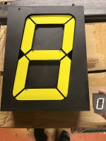
Picked up and old bus display sign off ebay a few weeks ago. It uses flip dot displays.
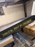
A quick count of the "pixels" and its 7 X 84 - plenty of pixels to go at.
Last night I got around to opening it up to see what's inside:
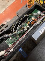
There is a controller board and then 3 flip dot boards all daisy chained together each one is 28 X 7 pixels. So I think I can make 3 clocks out of this.
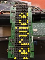
Each board has a set of cmos logic chips, so I'm hoping I can just hook up to this logic and use the board as it is.
There is no documentation, so I'll have to try and figure out what the chips do.......
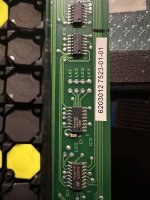
It looks like there is a row driver circuit (for the 7 rows) and then 4 identical column driver circuits for the 4 X 7 columns? I think.
All of these look to be controlled by 4 logic chips, So far I've identified these as a quad latch, a 2 to 4 line decoder and 2 binary counters.
I guess the binary counter will count the rows 1-7 and the second ic for the columns 1-7. Assuming the columns are in 4 banks of 7 then I think the 2-4 line
decoders will specify which bank 1-4 of columns to address.
The quad latch seems to be input control signals as I have figured it's 4 inputs are connected to the header connector on the PCB.
I've also been working on some other clocks:
1. Revisit the flip digit clocks I made a few of a few years ago, so decided to make a few more. Here's the first one.
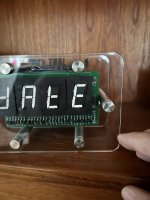
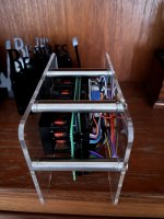
Really nice satisfying click as the magnetic 7 segment displays change over.
2. I also go around to finishing my "Music Art" clock - this goes and finds your chosen artists record covers from the internet and displays them along with info about the recording, as well as the usual date/time stuff
I set it off overnight and it picked up several 100's of different Beatles artworks! It can grab album covers - front, back, record sleeves, record labels, singles, ep's, CD's etc. All configurable. Any artist/band/musician to choose.
I may make more of these to sell next year.
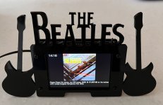
Thanks to @Colywobbles for the superb design on the cases/frames for the last 2!
Picked up and old bus display sign off ebay a few weeks ago. It uses flip dot displays.

A quick count of the "pixels" and its 7 X 84 - plenty of pixels to go at.
Last night I got around to opening it up to see what's inside:

There is a controller board and then 3 flip dot boards all daisy chained together each one is 28 X 7 pixels. So I think I can make 3 clocks out of this.

Each board has a set of cmos logic chips, so I'm hoping I can just hook up to this logic and use the board as it is.
There is no documentation, so I'll have to try and figure out what the chips do.......

It looks like there is a row driver circuit (for the 7 rows) and then 4 identical column driver circuits for the 4 X 7 columns? I think.
All of these look to be controlled by 4 logic chips, So far I've identified these as a quad latch, a 2 to 4 line decoder and 2 binary counters.
I guess the binary counter will count the rows 1-7 and the second ic for the columns 1-7. Assuming the columns are in 4 banks of 7 then I think the 2-4 line
decoders will specify which bank 1-4 of columns to address.
The quad latch seems to be input control signals as I have figured it's 4 inputs are connected to the header connector on the PCB.
I've also been working on some other clocks:
1. Revisit the flip digit clocks I made a few of a few years ago, so decided to make a few more. Here's the first one.


Really nice satisfying click as the magnetic 7 segment displays change over.
2. I also go around to finishing my "Music Art" clock - this goes and finds your chosen artists record covers from the internet and displays them along with info about the recording, as well as the usual date/time stuff
I set it off overnight and it picked up several 100's of different Beatles artworks! It can grab album covers - front, back, record sleeves, record labels, singles, ep's, CD's etc. All configurable. Any artist/band/musician to choose.
I may make more of these to sell next year.

Thanks to @Colywobbles for the superb design on the cases/frames for the last 2!
Spent most of the day, figuring out how the logic controls work, pretty simple, yet clever stuff. I think it has 4 controls:
1. A row advance that moved down each row - 8 of them,
2. A Column advance that moves down each of the 84 columns
3. A Set/ Unset - determines whether to set (yellow) or unset (black) the digit at the current row/col intersection
4. A Reset, that resets back to Row 1 Col 1.
The coils use a higher voltage than the 5v/3.3v logic chips - I'm guessing 16-19v. The HV circuit is split out into 2 pins on the header connector.
One is for the Source IC's TD62784A and the other is the HV connection to the Sink IC's ULN2803A.
There is nothing in the logic on the board that (as far as I can see), can pulse the HV to the coil. If all the HV was connected permanently, then which ever coil was active on the current row/column would get power all
the time. This would burn the coil out.
So, my guess is that the Source IC's HV supply is actually not on most of the time, and is only pulsed for a 1ms interval, after the 4 control lines have all been set.
That's going to be a bit of a challenge to control from my microcontroller, Ive used a MOSFET to switch something to ground, but this needs to switch the line to +16-19v. Will require a different MOSFET to drive high and probably a pre-drive
transistor too.
Next step is to prototype something up,
I will have a go at a proto board to fit over the top of the PCB above the flip dots, there is about 30mm height and 280 wide to go at:
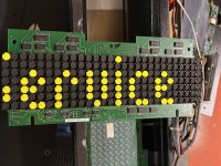

Took a few days, but I've finally disassembled the control logic, and then designed a control board which will control this display. it should fit on top of the existing PCB:

I've got an ESP32s as the brains, a Real time clock module with battery backup to hold and remember the time, a buck power board to provide the higher voltage for the coils.
I've added a temperature and humidity sensor and a buzzer, as used in one of my other clocks. The output to the display board is via a 595 Shift register and a header connector
on the PCB. The pulsing HV is controlled by a FET which in turn is switched on by a transistor. I've also added 2 RGB leds, could be used for example to flash or pulse every second.
Now just got to wait for the PCB to arrive from the factory. Will update the thread once I've got it hooked up and programmed.
Go big or go home mate
call me “Big Al”
WANT ONE ! Put me on list !
Me too I’m in 
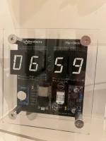
Latest flip digit clock.
I’m making a small run if anyone wants one.
Configurable via wifi. Shows time, date, year, seconds, temperature, humidity. Leds pulse (can switch these off if not wanted). You can configure what is displayed and for how long. You can change the speed of the led pulses. You can configure it to go off “quiet” at night time. Battery clock backup, or connect to your wifi network for accurate internet time updates.
£120 posted UK.
Video here :

Come on Alan. Where’s yer Banana  for scale
  .
.
These look really cool. I still haven’t built the last one i got from you!!
These look really cool. I still haven’t built the last one i got from you!!

