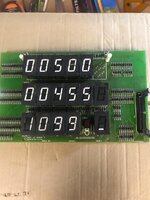
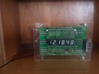
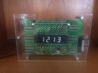
Alan, good work, this topic has spiked my interest for some time. I was wondering if this could be adapted to graft onto a real EM to display time using the reels when the game is over, perhaps even better have an option to alternate displaying a last remembered hi-score. Sound feasible?
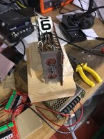
I've been playing around with one of my EM's to see what is involved in achieving this. In theory it seems easy, but in practice it's turning out to be pretty tough, but not impossible.
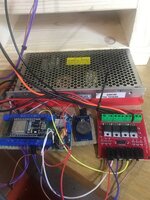
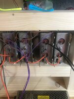
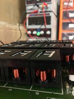
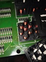
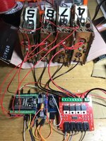
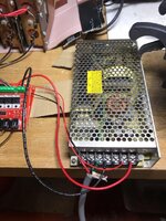
I've got the 4 score reels being controlled in-situ by the controller and 24v DC power supply from the 'clock'. This works fine when the machine is switched off. It's not good when the machine is switched on as we could potentially have 25v A/C and 24V DC from separate power sources on the same line... Not good. So I put in a relay, and then hooked up a feed from the pinball to detect when the power is on in the pinball machine. This needs an opto-isolator to convert a simple feed from either the 6v or 25v rail into a signal I can use. I modified the software to switch an opto isolated relay and disengage the 24v DC power to the reels as soon as the power to the pinball is switched on. So far so good.
I then realized that I can then no longer control the reels as the pinball is using 25v AC and I'm using DC only mosfet circuits to move the reels. I could go back to using opto isolated relays to solve this problem, but the crappy relays from china are not up to the job, I could beef these up by adding a better relay that can handle the current. The other option and the one I went for initially was to tap off a DC supply from the 24V ac using a bridge rectifier - a bit crude but it works (could do with more on here like some smoothing caps etc). I then realised it's not that easy to separate out the wires and feed to the 4 score reels from the A/C feed to make them DC. So back to square 1 - it is going to be easier to just control with A/C - so back to the relay idea. I've found some 12v 100A automotive relays, not ideal as I've got
24/25 or 6v. But I'll figure out a way.
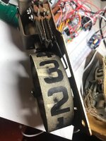
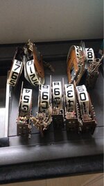
Then I went on to figure out how to tell where the reels are - the way the EM clock works, is it initially zeroieses each reel - checks the zero position switch then keeps a count. So, I used 4 way opto isolator to try measure the 4 switches, one on each score reel. This is tricky as the switches are wired in series to each other, so I have to figure out where to connect the power in and signals out wires, needed to study the schematic, quite a bit of messing about here. Also to throw a spanner in the works there is a 'hold' relay that also connects across the 10's unit zero position switch. That might be a problem! I may have to stick in a diode to kill that for my purposes but still allow it to function for the game itself.
Im not onto the game oveer relay, again I need to get a signal off that relay to figure out if we are in a game or not! Not sure if the game over is the right one, or maybe on of the other relays would be better. Still studying. Again this will need an opto isolator.
So, so far I have got:
1 24v PSV
1 Esp32s controller & 5v psu step down board.
1 Real time clock module.
6 Opto isolator input circuits - 4 for the score reels zero position, one for pinball power and 1 for game over
5 output opto isolated relay circuits. One to switch on/off the DC power. 4 for the score reels to go via beefy additional relays.
a ton of wires into and out of the pinball machine.
It's starting to look rather unwieldy! Might have a sit back and see if there is another way.............
