A bit of interest in this, so as requested here is a thread of it's own.
I got the idea from @James who sent me a link a few weeks ago to a guy who had done a clock made out of old EM reels.
The thought stuck in my mind and I wondered if I could do it myself from scratch.
I decided to do it totally from scratch myself, the woodworking, electronics and the arduino programming. I wanted a clock that told the time, got the latest time off the internet if connected to wi-fi and also adjusted for BST/GMT.
Youtube video here:
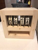
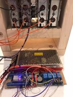
Parts are pretty simple:
4 old score reels
From left to right in the above picture:
ESP32s - like an arduino but has built in wi-fi and is much better to work with.
Voltage regulator board, set to output 5V
RTC module - real time clock, with battery backup
4 channel Opto isolated relay board
Here is a full parts list to build an EM clock :
4 EM score reels. Any will do, as long as they are in working order
ESP32s board:
https://www.ebay.co.uk/itm/ESP32-ES...ooth-Antenna-UK/143297558340?epid=20031754719
Holder for the ESP32s – note this item needs to be cut in half to fit the esp32s, as this is made for an Arduino nano board (I have not yet found a supplier who produces a terminal board that fits the ESP32s). Another alternative is to just use dupont connectors directly onto the pins of the ESP32s. I cut in half with a fine saw and then glue to a base - wood or card.
https://www.ebay.co.uk/itm/Nano-Ter...-ATMEGA328P-AU-Module-Board-6-HO/233591681563
Real Time clock Module
https://www.ebay.co.uk/itm/fit-For-...on-RTC-Real-Time-Clock-Memory-UK/164154985457
Battery for RTC module
https://www.ebay.co.uk/itm/5-X-Supe...oundMax-3-VOLT-LITHIUM-BATTERIES/293566166984
Adjustable Voltage Regulator – note you will need to adjust the output voltage of this to be 5V, they come unadjusted and so it will give out around the input voltage (24v) and will damage the ESP32 and the Relay board if you don’t adjust first!!!!
https://www.ebay.co.uk/itm/5A-DC-DC...lt-Power-Supply-Converter-Module/192473544494
Note: this next part has been superseded! see below
4 Way opto isolator relay board.
https://www.ebay.co.uk/itm/5V-DC-Re...olation-arduino-pic-pi-avr-NewUK/190950013824
I’m going to use a solid state mosfet driver board instead. the em relay coils will soon destroy the relay switch contacts. as i’ve found out. so need a more elegant solution.
will list part or parts as soon as i’ve sourced and tested. looking at IRF540 or similar.
https://www.ebay.co.uk/itm/4-channe...fet-switch-module-for-arduino-9H/224017014979
24v power supply – go for 5A or 10A.
https://www.ebay.co.uk/itm/Regulate...18V-24V-36V-48V-Universal-PSU-DC/151886747221
Hookup wire, cable ties, wood for housing.
Software available from me for the ESP32s. You can either:
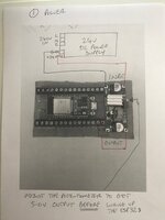
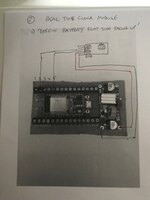
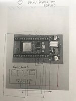
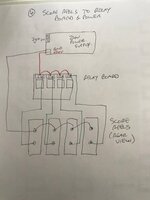
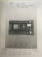
Wiring Diagrams:
I decided easiest to do it in logical stages:
Software Configuration:
I came across two issues with the score reels, to which I have developed a software solution:
1. Firstly, on the 4 score reels I had, I noticed they worked differently with respect to how the zero postion switch works. 2 of the units had the switch normally open, until the reel is at position zero, then the switch is closed. The other two reels were the opposite, ie. the switch was normally closed until the score was in the zero position, then it becomes open! So, I have allowed for this, and you can configure what type of switch you have on your score reels. Open or closed when in the zero position.
2. The second issue I had, what that different score reels take differeing amounts of time to be activated, so so I have also allowed a configuration to set the time each coil is energised, in multiples of 100 milliseconds, ranging from 1 - 10. from 1/10 second to one whole second.
All these settings are configured in the wi-fi config menu, which is accessed from the ESP32s. You can connect to the device even if it is not conneccted to your wifi network - it creates its own wi-fi access point, which you can connect to from your phone.
Here is a screen shot of the config page:
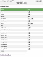
In My system, Reels 1 & 2 have a zero position switch that is closed until the score hits zero and then it is open. Reels 3 & 4 have a zero position switch that is open until the score hits zero and then it closes.
Reels 1,2 & 4 get 1 burst of 100 milliseconds to energise the score coil and turn the score. Reel 3 gets 3 lots, 300 milliseconds. it's a slower reel.
I Hope this helps. Happy to assist and answer and questions.
I got the idea from @James who sent me a link a few weeks ago to a guy who had done a clock made out of old EM reels.
The thought stuck in my mind and I wondered if I could do it myself from scratch.
I decided to do it totally from scratch myself, the woodworking, electronics and the arduino programming. I wanted a clock that told the time, got the latest time off the internet if connected to wi-fi and also adjusted for BST/GMT.
Youtube video here:


Parts are pretty simple:
4 old score reels
From left to right in the above picture:
ESP32s - like an arduino but has built in wi-fi and is much better to work with.
Voltage regulator board, set to output 5V
RTC module - real time clock, with battery backup
4 channel Opto isolated relay board
Here is a full parts list to build an EM clock :
4 EM score reels. Any will do, as long as they are in working order
ESP32s board:
https://www.ebay.co.uk/itm/ESP32-ES...ooth-Antenna-UK/143297558340?epid=20031754719
Holder for the ESP32s – note this item needs to be cut in half to fit the esp32s, as this is made for an Arduino nano board (I have not yet found a supplier who produces a terminal board that fits the ESP32s). Another alternative is to just use dupont connectors directly onto the pins of the ESP32s. I cut in half with a fine saw and then glue to a base - wood or card.
https://www.ebay.co.uk/itm/Nano-Ter...-ATMEGA328P-AU-Module-Board-6-HO/233591681563
Real Time clock Module
https://www.ebay.co.uk/itm/fit-For-...on-RTC-Real-Time-Clock-Memory-UK/164154985457
Battery for RTC module
https://www.ebay.co.uk/itm/5-X-Supe...oundMax-3-VOLT-LITHIUM-BATTERIES/293566166984
Adjustable Voltage Regulator – note you will need to adjust the output voltage of this to be 5V, they come unadjusted and so it will give out around the input voltage (24v) and will damage the ESP32 and the Relay board if you don’t adjust first!!!!
https://www.ebay.co.uk/itm/5A-DC-DC...lt-Power-Supply-Converter-Module/192473544494
Note: this next part has been superseded! see below
4 Way opto isolator relay board.
https://www.ebay.co.uk/itm/5V-DC-Re...olation-arduino-pic-pi-avr-NewUK/190950013824
I’m going to use a solid state mosfet driver board instead. the em relay coils will soon destroy the relay switch contacts. as i’ve found out. so need a more elegant solution.
will list part or parts as soon as i’ve sourced and tested. looking at IRF540 or similar.
https://www.ebay.co.uk/itm/4-channe...fet-switch-module-for-arduino-9H/224017014979
24v power supply – go for 5A or 10A.
https://www.ebay.co.uk/itm/Regulate...18V-24V-36V-48V-Universal-PSU-DC/151886747221
Hookup wire, cable ties, wood for housing.
Software available from me for the ESP32s. You can either:
- send me your esp32s and I’ll upload and test the board for you & send back, or
- I can provide source code and you can install the Arduino IDE, install ESP32 board extensions & the various libraries that are also used, compile and upload it yourself. I’d only recommend this if you are familiar with Arduino programming!
- I can provide an ESP32s board with the s/w pre-loaded, fully tested for £13 UK posted.
Wiring Diagrams:
I decided easiest to do it in logical stages:


Software Configuration:
I came across two issues with the score reels, to which I have developed a software solution:
1. Firstly, on the 4 score reels I had, I noticed they worked differently with respect to how the zero postion switch works. 2 of the units had the switch normally open, until the reel is at position zero, then the switch is closed. The other two reels were the opposite, ie. the switch was normally closed until the score was in the zero position, then it becomes open! So, I have allowed for this, and you can configure what type of switch you have on your score reels. Open or closed when in the zero position.
2. The second issue I had, what that different score reels take differeing amounts of time to be activated, so so I have also allowed a configuration to set the time each coil is energised, in multiples of 100 milliseconds, ranging from 1 - 10. from 1/10 second to one whole second.
All these settings are configured in the wi-fi config menu, which is accessed from the ESP32s. You can connect to the device even if it is not conneccted to your wifi network - it creates its own wi-fi access point, which you can connect to from your phone.
Here is a screen shot of the config page:

In My system, Reels 1 & 2 have a zero position switch that is closed until the score hits zero and then it is open. Reels 3 & 4 have a zero position switch that is open until the score hits zero and then it closes.
Reels 1,2 & 4 get 1 burst of 100 milliseconds to energise the score coil and turn the score. Reel 3 gets 3 lots, 300 milliseconds. it's a slower reel.
I Hope this helps. Happy to assist and answer and questions.
Last edited:

