May 2015
VARIOUS FIXES & UPDATES
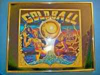
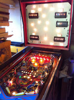
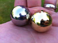
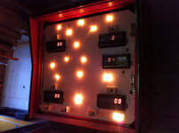
I'm just so excited now that my GOLD BALL is working and playable!

Hey,
@andy! It's working again!

Another pin back from the dead!
FLIPPER OVERHAUL
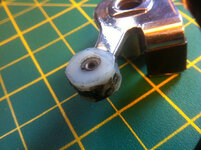
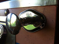
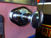
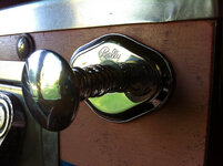
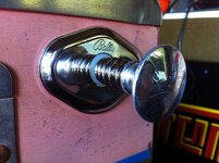
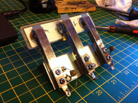
Looking pretty mullered I decided the nylon bearings needed replacing in the "linear" flippers. I've got a separate thread about this experiment so I won't go into detail, but I did manage to successfully create a pair of new "buttons" out of some 12mm Nylon-6,6 rod:
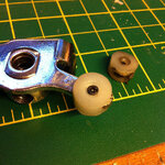
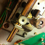
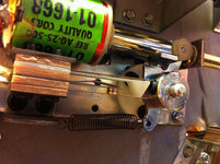
Along with the new buttons, the plungers got polished along with the coil stops, fitted new EOS switches, new main bushings, Nyloc nuts on the bushing and coil stop bolts, new Nyliners, one flipper got a new coil and both baseplates got an extra pair of sheet-metal screws that hold the flipper to the playfield bringing the total to 6. Flippers are notorious for working loose!
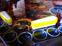
To complement the work underneath the flippers got new bats and yellow Superbands topside:
 METAL COVER PLATE
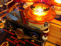
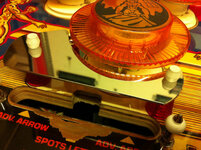
GOLD BALL has a custom metal cover plate that sits above and behind the special gold bullseye triple stand-up target bank. Mine was missing but
@astyy sent me a photo with rulers for scale. My friend cut me a new one on his CNC machine (
@astyy I've got one coming for you too... we just a few "technical gremlins" cutting the next one).
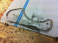
Looks awful but eventually it came off the CNC ok:
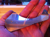
And after a bit of work with the Dremel and some polish it came up great:
 REBOUND SWITCHES & STAND-UP TARGETS
With the playfield upside-down on the cabinet I set about working on all the other switches:
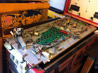
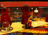
This is what all the rebound switches looked like to start with:
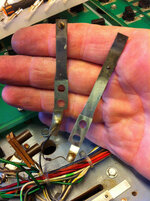
But after a little "Dremel Love" they came up a treat! It's such a small thing but it's another little bit of bling that catches and reflects the glow from the GI lamps and just makes the game look more beautiful. It says "I'm loved.":
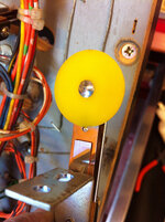
Similar lover was also lavished on the 4 spot targets (3 yellow, 1 white) along with a little Novus #2 then #1 and some very careful buffing of the centre rivets:
 GOLD BALL BULLSEYE TARGET
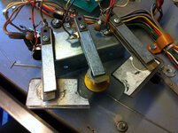
This was in a real mess. Notice each switch was only held on with one screw instead of two so they were free to move side-to-side:
First of all I popped out the rivets holding on the snapped "bridge" plastic. I popped a cable tie through each just to keep the bits together as they tend to fall apart:
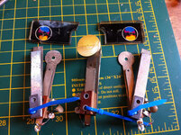
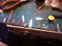
Each switch was then taken apart in order and the metal parts polished clean with the Dremel:
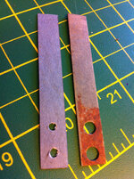
I also found my first use for the fishpaper from my group buy. At the back of each stack before the thick steel brace bar was a layer of fishpaper. These must have got wet at some point as they were rusty and had made a mess of the fishpaper. The fishpaper itself was still intact and serviceable, but I thought it'd be nice to make new. It was cut using a scalpel and the holes made with 3mm drill bit using the steel plate as a template:
Once all the switches were done it was time to do something about the broken plastic. My ultimate goal is to make a reproduction using some tough 4 or 5mm Lexan but for now I simply cut a match out of 3mm Lexan and used it to cross-brace the original.
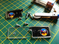
As the original rivets were knackered, and too short with the extra 3mm Lexan, I bought some 8mm long M3 bolts with rounded hex heads and matching Nyloc nuts. These look very smart and not too different from the rivets. Most importantly no sharp edges to knick the ball when struck:
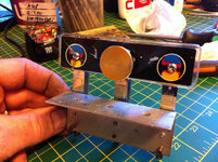
And the rear looking all shiny too:
 KNOCKER
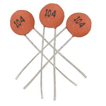
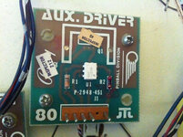
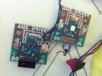
I don't have a photo of the knocker coil but it was a sorry sight. Bulging a little around the middle with the wrapper brown from overheating, the plunger did not move freely at all. It was actually very sticky rather than stuck so at some point someone must have thought lubricant of some sort was a good idea. Whatever it was over time it dried out and congealed. After dismantling, polishing the plunger and cleaning the coil sleeve it still didn't slide smoothly. Definitely a knackered coil. Luckily I had a spare AQ-26-1200 from the outhole kicker on the junk PARAGON playfield I have. Tested out just fine. Popped it all back together (mental note: need to get a proper coil-stopless sleeve with extra collar) but still no knock in test mode. Time to reference the schematics! This coil is activated by SCR Q41... which is missing from my driver board along with R88 and CR8! They had been removed so cleanly and there's no trace of scorching so I assumed they were never fitted. Use a TIP102 for Q41, a 1N4007 for CR8 and a pair of 620 Ohm resistors in parallel (total 310 Ohms) for R88 as I'm out of 300 Ohm resistors (on order with a bunch of 50nF ceramic disc capacitors for switches):
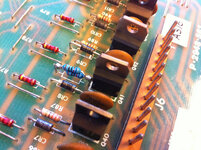
Voila! Knocker working again. Not very loud though. Might try and beef it up a bit with a more lively coil and move it from the rear-side of the cabinet to the front where the coin box would sit.
MEMORY BACKUP BATTERY
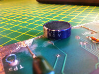
The rechargeable NiCd on the MPU is long gone after spilling its necrotising guts all over the board, so I need a better replacement. I don't like the remote AA battery boxes - it's another set of batteries to forget, so I decided to try a Super-Capacitor. These have a ridiculous level of storage for a capacitor and therefore behave very much like a battery without any issues related to leakage. The are ideal for low current application like power SRAM memory chips.
To mount the memory backup super-capacitor a 1mm hole was drilled adjacent to the ground connection for the original battery. The negative terminal was soldered to this to anchor the battery then a short run of red wire connects to the other original battery point where charge is delivered via resistor R12:
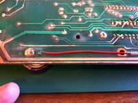
This super-capacitor is 1uF at 5.5V and should supply enough power to the SRAM for at least a month. Recharging should take around an hour so as long as the game is on once a month for at least an hour we're good:
 INTERMITTENT BULLSEYE
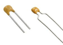
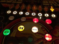
I started to notice during gameplay that when the ball struck the gold bullseye it would advance the arrow but rarely light the adjacent G-O-L-D-B-A-L-L letter. After consulting the schematics I realised this switch was missing it's 0.05uF ceramic disc capacitor (you can see it's missing in the photos above). I didn't have any in stock so blagged this from the junk Paragon playfield again. If you want to know about why capacitors are connected across certain switches read
3m. When things don't work: Switches and the Switch Matrix.
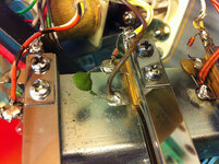
The old green capacitor from Paragon has seen better days but it measured exactly 50nF on the ESR meter and I will replace them all when the new ones arrive. It has however totally fixed the letter spotting problem! I guess the switch closure was so fast that the MPU only had time to register it long enough to run the interrupt code to advance the arrow but not light the letter. With the capacitor the switch closure signal is slightly elongated.
