What's new
Pinball info

Register a free account today to become a member! Once signed in, you'll be able to participate on this site by adding your own topics and posts, as well as connect with other members through your own private inbox!

In Progress 1983 Bally GOLD BALL - Further Adventures in Budget Restoration

Nedreud

Registered
10 Years
Joined
Feb 12, 2013
Messages
3,092
Location
Aldershot, UK
I love the smell of a fresh shop log in the morning!

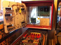
They said it would happen. And it did. You can't buy just one pinball machine. It always leads to others. But now I've filled my humble pinshack to capacity! So, he she is, my 1983 Bally GOLD BALL:
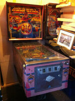
farm4.staticflickr.com_3858_15186179165_25da6ae10d_c.jpg

No idea really what states she's in mechanically or electrically (I seem to have started referring to GOLD BALL as "she" - looks like she's a girl, then). A quick look reveals everything to be there. Playfield looks good, no missing parts or obvious major damage. Not found the gold ball yet. Itching to get the MPU on the test bench...
 
I view my collection of pins as more of a family. GOLD BALL seems have become female, a mother - maybe because she's pink (even the area under the legs has faded from red to pink!). PARAGON is big and beastly, and therefore definitely a man - the father. VECTOR is just like a stroppy, temperamental teenager, but also very cool :cool:
 
RESISTANCE.IS.FUTILE

MUST.FIX.DEAD.BOARD

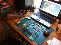
And so it begins! I just can't resist. PARAGON is still a pile of bits but I simply have to get the MPU working in GOLD BALL!

image.jpg

image.jpg

I even followed my own instructions on the PARAGON shop log as to how to wire up the test rig again!
 
Things noticed so far whilst having a poke around. In no particular order:

  • No gold ball :( not a surprise!
  • 2 pairs of different legs: one black pair, one grey pair
  • No latch arm or key on coin door lock
  • No backbox lock
  • Missing metal lift channel on backglass
  • Missing most of plastic backglass trim
  • 5101 RAM chip missing on MPU
  • Playfield post replaced with wooden dowel!
  • Slingshot coil disconnected and rather brown
  • Standard household 13A and 5A fuses on power supply board
  • Lots of bits of electrical connector block in playfield loom
  • Botched earth strap replacement
  • Extra feed direct from PSU to GI
  • Botched soldering in flipper coils
  • Centre gold spot plastic snapped in half
  • All rubbers fully perished and crumbly
  • One white, one transparent blue flipper buttons
  • Only one backbox bolt and one hinge
  • Snapped clip on one pop bumper cap
  • Odd looking big capacitor on sound board
Makes it all sound pretty bad but I'm still very happy! Playfield is good with only minor wear and a little planking for it's age. All the other plastics are in good shape. Pop bumpers in great condition as is much of the under-playfield mechs, loom and electrics. Backglass could be worse. Cabinet is ultra faded but solid and in good nick - no major dings. No acid damage on MPU at all - potentially only one of its kind! The weird lamp driver / voltage regulator / solenoid driver board looks good (would be hard to replace as only ever fitted to GB and Grand Slam).

All-in-all pretty much the same start as PARAGON and that's in the road to recovery.

GOLD.BALL.WILL.SURVIVE
 
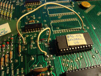
Started to probe a bit deeper on the MPU. It's got replacement EPROMS so no U1 just U2 and U6. U2 is a 2532 and U6 a 2732 so the jumpers should be as follows (from http://techniek.flipperwinkel.nl/ballyss/rep/index3.htm#35roms):

4-12, 7-8, 10-11, 13a-14, 16a-29, 31-32, 33-35 cut 13-15

Found one mistake. Some had bridged 16-29 and not 16a-29. Didn't make any difference - still got a solid green test LED. Next job is to pull all chips and reseat U6, U9 and U11. If that doesn't work then pull all chips and start testing for duff tracks. I've got plenty of U10/11 chips (6821 PIA's) as I bought 10 from China when I fixed PARAGON but will need another 5101 static RAM eventually. I may try swapping in the PARAGON chips which are all known good but it will probably mean reverting the jumpers back to factory as I think U1/2/6 are the original masked ROMS.
 
Well this MPU is going to be a trickier little bugger than the one from PARAGON. Problem is no sign of acid damage, it's either a duff component(s) or dry joint. I've tested the GND and VCC to all chips and test points for continuity, and across many other points throughout the circuit. All good. All components look ok; that is, no obviously burnt or bubbled. And I can't see any tell tale signs of dry joints. Of course there could be and I may have to reflow the whole board. But...

Being a bit more systematic about it I did the following things:

  • Pulled all chips and polished the pins (noticed U10 had a pin soldered back on!)
  • Tested voltage at U9 pin 40 - low before power on then high after a second (same on pin 2) - RESET CIRCUIT working
  • Shorted R1/R3 junction to ground - U9 pin 40 goes low - RESET CIRCUIT working
  • Reseated U6 EPROM, U9 6800 CPU and U11 6821 PIA for "bare-bones" system - no LED flashes
  • Put in a brand new U11 6821 PIA - no LED flashes
  • Put the U9 6800 CPU in working PARAGON MPU board - got 6 flashes, chip is good
  • Put the U11 6821 PIA in working PARAGON MPU board - got 6 flashes, chip is good
  • Put U9 6800 CPU and U11 6821 PIA from PARAGON into GOLD BALL MPU - no flashes
From this I'm narrowing it down, although not conclusively, that the most likely problem is a duff U6 EPROM. Next test is to remove all the custom jumper wires and replace the original factory jumper settings. Then I can pop in the U1, U2 ad U6 original 9316 masked ROMS from PARAGON. If the CPU boots and I get all the LED test flashes then I know the board is good and the GOLD BALL ROMS are chuff.

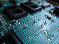
Mmm... just ordered some Dupont jumper wires from eBay commonly used for Arduino/RaspberryPi prototyping. By soldering in 0.1" header pins onto each "E" jumper point I can re-jumper the board by just moving the wires around.

Drat... was just looking at the schematic and realised that E16 and E16A are connected to each other so no difference jumpering 16-29 or 16a-29.

Gut feeling is still duff EPROMS. They've only got white paper sticky labels over the erasing window instead of proper blackout labels. EPROMS would have eventually been erased or gone a bit "strange" if left out in the daylight too long.
 
White sticky labels should be fine, since as long as it blocks out the UV.... saying that i have seen failed ROMS where the labelling was starting to come away... have even seen ROMS 3 or 4 years old with no covering at all working fine :eek: :D
 
Yeah, could be @Paul. Who knows? Could still be a fault on the board but the more I prod and poke the less it seems likely. My money's still on duff ROMS. We shall know shortly... soldering iron is warming up right now to get the jumpers put back to factory.
 
http://www.ebay.co.uk/itm/321518317248 - original manual if you havent got one (and have deep pockets!!)
Ouch! I was going to put together a Wanted ad some of the various bits and bobs I know I need for GB and a manual was to go on the list. Both Paragon and Vector came with manuals and I picked up a mint official Bally ELECTRONIC PINBALL GAMES REPAIR PROCEDURES at UKPP last year for only a fiver! I ain't parting with £32 for a manual! Sheesh...
 
Sounds like a duff U9 6800 CPU, which will probably be why the 5101 memory chip was robbed...

You're welcome to bring the board down to SWL and try it with the relevant chips. :cool:
 
POOP :(

Cleared off all the custom jumpers and re-instated the factory defaults. Only installed U6 9316 ROM, U9 6800 CPU and U11 PIA, all known working good from Paragon, but still the LED is on constantly, no flashes. ****. Still doesn't prove the U6 ROM from Gold Ball isn't knackered but it does prove the Gold Ball MPU is still turked somewhere because if I switch U6/9/11 back into the Paragon MPU it boots up with a flash.

So... time to start testing traces and looking more closely at the RESET circuit. Hunch now is duff trace in the logic area between CPU, ROMs and PIAs, although one of the fixed non-socketed chips could well be toast.

Maybe have to get the digital oscilloscope for this one!

Be gone ugly jumpers:

farm4.staticflickr.com_3850_15197044571_58c2723e07_c.jpg

Hello shiny new factory-spec jumpers:

farm4.staticflickr.com_3889_15197027201_c38cdb4d68_c.jpg

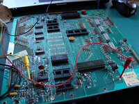
On the test bench. Still no flashes...

farm6.staticflickr.com_5566_15013496988_caf9bb27b3_c.jpg
 
What?!?!? Spend money?!?!? Where's the BUDGET in that? :eek:

I'm not defeated by these minor hurdles. It's just simple solid-state stuff. Considering the board isn't acid damaged it shouldn't be too hard to get going.

I also like a challenge. The electronics are the part I find most enjoyable. I like the shiny stuff too but I'm most comfortable with the electrics and electronics.
 
FOUND IT!!! I think...

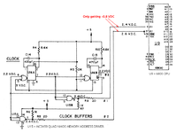
Took around 3 hours but finally traced that non-socketed chip U15, an MC3459 QUAD NMOS MEMORY ADDRESS DRIVER, that forms the CLOCK BUFFER for the 6800 CPU is duff. At least I'm pretty sure it is because it's got a clock signal going in but it's not producing the buffered output. Basically, there's no clock signal being sent to the CPU. No clock, no processing, no computer.

Here's a crop of the relevant section from the MPU schematic:

Bally_35_MPU_CLOCK.png

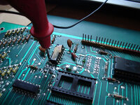
The CLOCK section seems good (chip U16) but I'm not getting the correct outputs from U15. Digital oscilloscope time! I've removed the suspect U15 so that I can check with certainty that U16 is doing it's thing. Here I'm testing pin 7 which feeds pins 9 and 10 on U15. Should be getting 2.3VDC and some sort of pulsed clock signal:

farm4.staticflickr.com_3867_15020603117_dd685b5eb0_c.jpg

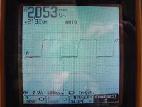
Checking the 'scope I see 2.192VDC pulsed at around 1,750ns or about 0.5 MHz:

farm4.staticflickr.com_3851_15204121491_3d8d3c26fe_c.jpg

Taking U15 off the board was a bitch as it's soldered both sides. I'd love to pull U15 off the Paragon MPU but worry the process will damage it. I've ordered a couple of equivalent 74S37 from eBay for just a couple of quid. Should be here on Saturday...
 
Nice work Peter. I really need to learn more of this sort of stuff. I'm slowly learning to read the schematics but it's a pretty steep learning curve.
 
I love it, so retro! I'm a software engineer but grew up with solid state, so it's nice to go back and fiddle with stuff that borders the cross-over between electronics and computers. I like that to work out what this particular computer is doing I can stick a 'scope on it and watch the data signals going high and low.

So tempted to pull the U15 off PARAGON... MUST RESIST! I wonder if I've got some turned pin DIL sockets hiding somewhere? Should solder those in place first then pulling chips in the future will be a doddle.

For reference, chips U12, U14, U15, U16, U17, U18, U19 and U20 are soldered directly to the board unlike ROM chips U1-6, CPU U9, PIAs U10 and U11, NMOS RAM U7 and CMOS RAM U8 which have sockets.
 
White sticky labels should be fine, since as long as it blocks out the UV.... saying that i have seen failed ROMS where the labelling was starting to come away... have even seen ROMS 3 or 4 years old with no covering at all working fine :eek: :D

You don't really need to worry about that so much, erasing requires a specific wavelength UV light source at close proximity.

I work alot of early 80's games and it's pretty rare to have EPROM's with bit rot just because the label is missing (as they often are)

Nintendo don't even cover up the UV window on their games.

Theoretically, a few days in strong sunlight would erase an EPROM, or a few years under floro lights (so make sure your Gottlieb/Sega/Stern ROM's are covered)
 
That's pretty much my understanding @lukewells. I just wasn't sure about this MPU. It wasn't screwed into the backbox, just dangling by a single clip. It's got a label that says something like "Powers on ok. Gold Ball ROMS. 1987." It could have been worked on but the fault never traced and left sat on a sunny window ledge for years ;)

I'm not so suspicious of the U2 and U6 ROMS now. Those old EPROM devices are quite tough and hard to fry with static etc., so I'm sure once I get the CPU booting they'll be fine. Most likely culprit is the half of U15 used by the CLOCK BUFFER section. There could be other issues (I'm a tad suspicious about U14 too as I wasn't getting all the expected readings but that might be because the CPU isn't running) but not a lot is ever going to happen without a clock signal for the 6800!
 
Quick update: the turned pin SIL strips and SN74S37N chips arrived from eBay yesterday. Managed to have a quick hour this morning to solder in 2 rows of 7 pins for U15 and fit new chip. Didn't get off to a good start as I thought the dot indicated Pin 1 on the chip but it has a "U" cut-out instead so initially I fitted it the wrong way round! Luckily it wasn't damaged it (I bought two anyway) and checking the output with the digital oscilloscope again I know have a lovely buffered clock signal hitting the U9 6800 CPU on pins 3, 36 and 37.

But... no flickers or flashes on the diagnostic LED. Just on constantly. So, back to the drawing board to start tracing the fault to the next block in the circuit...
 
GOTCHA!

Did a bit of work during lunch break and have finally fixed the board! Re-seated the U6, U9 and U11 chips again and decided to go back to basics and double-check all the supply voltages and test voltages on the CPU. Well blow me! After a bit of man-handling and a small drop on the test bench the test LED gives an initial flicker and is no longer ON! Woah... that's odd...

  • Okay, let's pop U1 and U2 from Paragon back in. Oh no, LED back on (bad).

  • Pull U1 and U2 again. LED flicker and off again (good).

  • So start testing chip sockets... and then the LED is back to always being on (bad).

  • Mmm... just for the hell of it I decide to re-flow all the chip solder joints. BING BONG! LED off all the time.

  • Put U1 and U2 back in - still get initial flicker and then first proper flash. Flash 1! Woohoo! ROMS U1, U2 and U6 passing checksum tests!

  • Time to put U7 6810 RAM back in for the second flash. Oh dear... no second flash.

  • Decide to clean pins on U7 as they're pretty black. Notice Pin #13 has been snapped off! Fudge a temporary test connection with some nickel wire. Flash 2!

  • Replace U8 5101 CMOS RAM. Flash 3!

  • Replace U10 6821 PIA. LED reverts back to being on all the time.

  • Remove U10 and back to 3 flashes.

  • Refit U10 and LED stuck on again.

  • Bin original U10 and pop in a brand new one... Flash 4, 5 and 6! (Note that a Bally -35 MPU has two 6821 chips - U10 and U11 - but I only tested U11 in the Paragon board. Whoops.)

  • Flash 5 means U11 6821 PIA is good and Flash 6 means U12 555, the DISPLAY INTERRUPT GENERATOR, is good.
No Flash 7 yet as that only happens when the +43VDC for the solenoids is present, which it isn't on the test bench rig.


So, although there was no battery acid corrosion damage on this board there were a whole bunch of other problems:
Next task is to remove the factory ROM jumpers I fitted so the Paragon ROMS would boot and fit 0.1" header pins so I can easily re-jumper the board for any ROMS using some little 10cm jumper wires I got from eBay (£1.99 for 40):

$_12[1].JPG

Then I can fit and test the custom U2 and U6 GOLD BALL EPROMS. Then I can test the mains wiring in the cabinet. Then the PSU and rectifier board. And then the solenoid/lamp/regulator combo board. And then... and then... I can put the MPU back in the backbox and see if I can tease some life from GOLD BALL... :p
 
I was just watching (and rather enjoying) one of the very informative videos on YouTube that was linked at the end of mine when I noticed a name on the side of the multi-meter. I'm assuming this is you, @lukewells?

Nice work! Subscribed to your channel and watching more vids :D

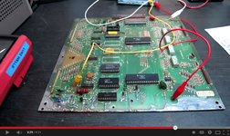
Check it out at 3:21:

JQS2nnnmEHk.png
 
You mean you'd not seen any of Luke's videos already? (ArcadeUK I think he is on YouTube)

I love those videos. I'm still strictly a n00b when it comes to Pins and electronics but by god they are so informative and a great way to learn. They've also inspired me to get more 'hands on' that I would have done normally.

Great work so far though Peter. Amazing the progress you've already made.
 
Ahh... I'd never made the connection that @lukewells is ArcadeUK. Good blog too but arcadeuk.com seems to be offline? I have seen some of them before. All very good!
 
Last edited:
GOTCHA!

Did a bit of work during lunch break and have finally fixed the board! Re-seated the U6, U9 and U11 chips again and decided to go back to basics and double-check all the supply voltages and test voltages on the CPU. Well blow me! After a bit of man-handling and a small drop on the test bench the test LED gives an initial flicker and is no longer ON! Woah... that's odd...

  • Okay, let's pop U1 and U2 from Paragon back in. Oh no, LED back on (bad).

  • Pull U1 and U2 again. LED flicker and off again (good).

  • So start testing chip sockets... and then the LED is back to always being on (bad).

  • Mmm... just for the hell of it I decide to re-flow all the chip solder joints. BING BONG! LED off all the time.

  • Put U1 and U2 back in - still get initial flicker and then first proper flash. Flash 1! Woohoo! ROMS U1, U2 and U6 passing checksum tests!
I had a similar Stern Mpu 200 board once, which had had the battery removed early enough to avoid corrosion damage, but had some repairs made to the traces with prototyping wire. After clearing that up, I tried some spare program chips in it, for Flight 2000, and found that with only the U5 & 6 fitted (out of the 4 E-Proms used) the board would complete the power-up Self-Test and then stop. I'd expected it to simply re-set and then stop. That made me wonder about how thorough the checksum procedure was with that game.
 
The U1-6 ROM checksum tests are very thorough. At least, that's my understanding. If a ROM is present the data is read out byte by byte and added to the next byte. At the end of the process the sum should be zero. The ROMS are programmed in such a way that each 512 byte block has special checksum bytes to ensure each block adds up to zero. If a single bit is changed the overall checksum for the ROM will not be zero. At this point the CPU can only conclude the ROM is bad and won't proceed to the next test (Flash 2 - U7 SRAM test).

The Stern MPUs are a slightly different in that some of them require U2 and U5/6 to get the ROM test 1st flash, but Bally MPUs only need U6 to pass this test (which is handy because if it passes with just U6 but fails after U1 is added then you know U1 is duff).
 
cpc give free delivery - i only ordered £9 odd the other day(14th),wasn't charged extra and got free 3=5 day delivery it arrived today

lot of ebay stuff tends to be dearer a lot of the time

good work on the board btw
 
Back
Top Bottom