What's new
Pinball info

Register a free account today to become a member! Once signed in, you'll be able to participate on this site by adding your own topics and posts, as well as connect with other members through your own private inbox!

Williams sys6 Green flipper rom images? And Help!

ronnie63

Site Supporter
5Years
Joined
Jun 8, 2015
Messages
2,451
Location
Scotland
Does anyone have or know where to get these 2 rom images?

Also I want to combine the 3 roms for the game onto one 2716, is it just a case of burning each image to the rom or do they need to be packaged up into one file first?

Thanks Ronnie
 
Sorry I think I have found them in the zip file I downloaded earlier! Also the gane rom seems to be in one file named .716, so guess it's already combined?
 
there is usually a text file in the zip file you downloaded with the roms,that should explain everything
 
Thanks guys,

Steve yes the text file explains somewhat apart from a typo stating flipper rom 2's location as ic27 instead of ic 17

Paul that's another usefull link explaining the roms etc

I think I have a grasp of what need to be done, hopefully replacing the 2 flipper roms will cure the problem I have with the door interlock switch, it will only go into attract with the door open! If that does not fix it then I will try the combined game rom

Cheers Ronnie
 
Ok I made a set of new flipper roms and the combined game rom but I still have a problem with the door switch function!

I'm now thinking it must be the switch matrix as the pia was dead on the driver board due to battery corrosion, but in the guide it says the door switches are not part of the matrix!

However I followed the guide to test the 7406 and 4049 chips in the matrix by metering the pins from ground both pin one's on the bottom 2 (7406 I think) were reading .2 which was a sign of being bad? I guess I have to change these anyway as they did have furry legs!

Only thing that was not right on the playfield was the tilt switch, all other switches worked fine in game play, But since I have tested these chips and swapped out the already socketed pia I'm getting sporadic swith activity and phantom scoring and targets resetting when they should not!

Fun and games for sure!

Thanks Ronnie
 
Right I have managed to get the playfield behaving again as it was but still no tilt functions from either the bob, door tilt or ball roll tilt, I'm putting this down to the matrix which hopefully will be resolved when I change the 4049's and 7406's

Moving on I traced the diagnostic wires to MPU 1J4 a 4 pin plug, and beside that 1J3 another 4 pin plug with one wire called display blanking, I thought at first maybe they were plugged in wrongly but no the plugs are keyed and fitted correctly. My problem must lie on the mpu either with IC5 or IC18 the pia, but the pia tested as good with the Leon test rom? I took a screen grab of the schematic area in case anyone can guide me a bit here? I'm a bit stuck.

Thanks Ronnie

Screenshot (6).png
 
1J4 connects the two diagnostic switches, Advance and Up/Down, along with the door open switch for 'Memory Protect'. That was new for the Lev. 6 board, a few games can apparently be used without it. The connector '1' re-appears on the other side of the drawing, lower l/h corner, connecting to IC24 (used as an inverter), J5, Test Point 3 and IC12. That gate of IC12 is concerned with controlling IC27, and R/W for the Cmos Ram.
 
Last edited:
1J4 connects the two diagnostic switches, Advance and Up/Down, along with the door open switch for 'Memory Protect'. That was new for the Lev. 6 board, a few games can apparently be used without it. The connector '1' re-appears on the other side of the drawing, lower l/h corner, connecting to IC24 (used as an inverter), J5, Test Point 3 and IC12. IC12 is concerned with controlling IC27, and R/W for the Cmos Ram.

Thanks Jay for taking the time to look, my problem is with the interlock switch, if it's open, game plays as normal, if it's closed displays go blank, if I then open it again displays go to zero (no attract) each further press of the interlock steps the displays through a count 1,2,3 and so on back to 0, at this point only resseting the power will return to attract with again door open! The interlock switch attaches to 1P4 pin 1. I have noticed if the game is in attract and I push the interlock switch briefly the first digit goes bright in the display before they go blank. None of the diagnostic switches do anything no matter what state the machine is in!

From that info in you post Jay I'm still not sure what to do

Thanks Ronnie
 
Is it certain that the wires in 1J4 are in the right slots?. That mention of a display digit briefly flashing brighter brings to mind my old Firepower - going into test had the displays and feature bulbs seem to momentarily 'lock' and brighten up before the blanking took effect and shut them off. I once made up a test box to plug into that connector, using the mounting rail and two switches from a broken-up machine, fitted into a plastic 'project box', with a good length of wiring. The lines in 1J4 are self-contained, connecting (or not) to their ground wire when the door is closed, Up/Down is in one position (I don't recall which UP) or Advance is pressed.
 
Last edited:
Is it certain that the wires in 1J4 are the right slots?. That mention of a display digit briefly flashing brighter brings to mind my old Firepower - going into test had the displays and feature bulbs seem to momentarily 'lock' and brighten up before the blanking took effect and shut them off. I once made up a test box to plug into that connector, using the mounting rail and two switches from a broken-up machine, fitted into a plastic 'project box', with a good length of wiring. The lines in 1J4 are self-contained, connecting (or not) to their ground wire when the door is closed, Up/Down is in one position (I don't recall which) or Advance is pressed.

Thanks Jay, I have double checked 1J4 and it's fitted correctly to the mpu 4 wires as you said the memory protect, ground and 2 up down door switches, there must be a fault on the mpu somewhere, I tried swapping out the 5101 and the batteries are retaining credits, not sure what do do from here.

Thanks Ronnie
 
Ok so I read a bit about the memory protect and verified J5 was made, I then probed TP3 to confirm it's hi low state with the interlock it was good, I then checked pin 1 1J4 had continuity to pin 1 1J3 that checked out also. Now it's bloody working! I can play a game with door closed, when I open the door it stays in attract until I press one of the door buttons and it seems I can go through tests but I have not grasped yet how that works! Anyway I'm no further forward with what was wrong and will it go wrong again!

Also the switch matrix had another meltown with things firing allover the place!, but I'm going to replace those 4049 and 7406's in the matrix and hope that cures that.

Cheers Ronnie
 
those 7406 7404 7402 7408 ics have had issues on every williams machine I've worked on - cosmic Gunfight, Disco Fever, Pinbot, Alien Poker - all of them had issues. Those chips are really in the firing line on the circuit - any playfield or cabinet wiring short takes them out pretty quickly
 
those 7406 7404 7402 7408 ics have had issues on every williams machine I've worked on - cosmic Gunfight, Disco Fever, Pinbot, Alien Poker - all of them had issues. Those chips are really in the firing line on the circuit - any playfield or cabinet wiring short takes them out pretty quickly
Thanks Alan yes and I guess the age of them don't help either! I have a good selection of ttl chips but you always find you never have the one's you need the next time!

Cheers Ronnie
 
Ah, the door switch should be linked to TP3, closing the door should bring TP3 to 5v, opening the door should drop it Low.

I can't help wondering if the door switch was actually being picked up as 'Advance' - pressing Advance with Manual/Down selected does have the effect you described, blanking out and 'waiting', with the Game On line active (Special Solenoids and flipper relay enabled). In fact, that's the entry point for diagnostics; pressing Advance again gets into display test, with this static if it's still Manual. Advance steps the display count with each subsequent closure, while the selection is Manual.

The diagnostic sequence is entry point (Advance & Manual), displays with manual/auto option, all feature lamps blinking (01 in credit display) with no 'Single Lamp' test, Solenoid test with Manual/Auto (02 on credit display, solenoid number on Ball in Play), switches closed (03 on Credit, all switches closed shown in succession on BiP), Bookkeeping/Adjustments (04 on Credit, 00 on Bip, Game i.d. on Player 1). Advance with Automatic steps to the next section, while Advance/Automatic in game over by-passes the diagnostics, going straight to 04/00/ 1489 #. Unlike later Williams hardware, it cannot step out of the Bookkeeping/Adjustment section, back to Game Over. It has to be switched off to exit.

Btw, chasing this has finally cleared up something I'd wondered about, the slingshot solenoids. The unusually high number of bumpers on this game exceeds the provision of 6 special solenoid drives, including the slingshots. Rather than than have one slingshot use the only remaining special drive, they're both assigned as normal solenoids, with an unused special drive. Whereas Stellar Wars has one of its five jet bumpers as the odd one out - but then they aren't all grouped together
 
Last edited:
@AlanJ just wondered if there were any either on the cpu or driver board that were regular offenders and might be worth changing when I'm doing work on the boards?

Thanks Ronnie
 
Ah, the door switch should be linked to TP3, closing the door should bring TP3 to 5v, opening the door should drop it Low.

I can't help wondering if the door switch was actually being picked up as 'Advance' - pressing Advance with Manual/Down selected does have the effect you described, blanking out and 'waiting', with the Game On line active (Special Solenoids and flipper relay enabled). In fact, that's the entry point for diagnostics; pressing Advance again gets into display test, with this static if it's still Manual. Advance steps the display count with each subsequent closure, while the selection is Manual.

The diagnostic sequence is entry point (Advance & Manual), displays with manual/auto option, all feature lamps blinking (01 in credit display), Solenoid test with Manual/Auto (02 on credit display, solenoid number on Ball in Play), switches closed (03 on Credit, all switches closed shown in succession on BiP), Bookkeeping/Adjustments (04 on Credit, 00 on Bip, Game i.d. on Player 1). Advance with Automatic steps to the next section, while Advance/Automatic in game over by-passes the diagnostics, going straight to 04/00/ 1489 #.

Btw, chasing this has finally cleared up something I'd wondered about, the slingshot solenoids. The unusually high number of bumpers on this game exceeds the provision of 6 special solenoid drives, including the slingshots. Rather than than have one slingshot use the only remaining special drive, they're both assigned as normal solenoids, with an unused special drive.

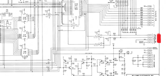
Funnily enough Jay the position of the coin door changes the state of TP3, the only thing I can think of is when I twisted J5 jumper wire that seemed to change everything! Have not checked again 1j4 pin 1 to TP3 but I will. And yes it seems the interlock was toggling the advance for some reason!

But the battle continues! This morning the game was mute! Grounding any of the 5 pins produced no sounds! But pressing the test button gave solid background sound! recycled the power and sounds were back! I have already recapped, new sockets, new sound rom, new 6802 new pia, nothing is ever easy!

I did read about the special solenoids on TW and as you said because it has 5 pops the slings are cpu controlled. And that brings me to another repair! one of the specials has in the past burnt a hole in the board! It's been repaired but the tip is floating in the hole!

Thanks Ronnie
 
I checked again and there is no continuity from 1J4 pin one to either J5 or TP3! That's strange because TP3 does alter with the interlock switch state 5v to 0v?
 
Sorry, but I was slightly misleading, earlier.

The Memory Protect line is inverted through a gate of IC24, so there probably wouldn't be a 'buzzer' continuity between the header pin and the test point or J5
 
Last edited:
Sorry, but I was slightly misleading, earlier,

The Memory Protect line is inverted through a gate of IC24, so there probably wouldn't be a 'buzzer' continuity between the header pin and the test point or J5

Ah that would explain it Jay, Still no idea why it now works! Driver board is on the bench having a scorch hole repaired!

Thanks Ronnie
 

Attachments

  • 09B0810D-24AA-4606-A38C-A1090C51F070.jpeg
    09B0810D-24AA-4606-A38C-A1090C51F070.jpeg
    104.3 KB · Views: 9
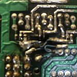
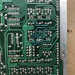
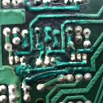
Hole now gone! New copper tracks, through hole rivets fitted and coated with solder resist. Good practice as I have a wpc driver board with similar damage to fix

55AC1738-FEDA-4272-AD24-E9E2E9FB338C.jpegFDA36E62-5F21-45E1-801D-3F3EB19AEBCF.jpeg
 
Nice looking repair😀

I had a similar issue on a Sys 11 board - always the pop bumper transistors that burn!!!
I actually cut the damaged section out and replaced with an undamaged piece from an unrepairable board.
Didn't look as good as that though😄
 
Nice looking repair😀

I had a similar issue on a Sys 11 board - always the pop bumper transistors that burn!!!
I actually cut the damaged section out and replaced with an undamaged piece from an unrepairable board.
Didn't look as good as that though😄

Thanks Andy, I used some isopon fibreglass stuff for the hole, I think the wpc will be trickier! Ideal if you have a scrap board to hand, I guess it does not need to look pretty
 
Back
Top Bottom