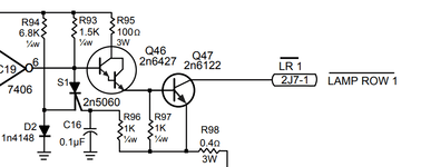
I've done the Mosfet conversion a few times but was wondering if it's necessary if I fit LEDs instead of incandescemts.
Will I still get the heat generated by the 27ohm resistors?
Will I still get the heat generated by the 27ohm resistors?
Very comprehensive, and very interesting - is there a way to work out the forward voltage & current without the data sheets? The reason I ask is I am planning to omit a circuit & drive some LEDs directly under Arduino control (via a relay, not direct) & based on what you have said, I suspect it may be sensible to add a resistor in the circuit. There is a pic of the circuit that I will not be using in this thread https://www.pinballinfo.com/community/threads/building-a-topper.52422/ - can't make out what that resistor is, but I may just re-use it.Hi,
I'm not familiar with what you mean by MOSFET conversion. Do you mean that you are replacing the old power transistor with MOSFETs?
If so, a (properly selected) MOSFET will be easily be able to drive an LED. Having said that, the original power transistors will be more than able to drive LEDs too. However, it's not as simple as that (it never is).
The main difference between a transistor and MOSFET is that transistors are current driven devices whereas MOSFETs are voltage driven. Another difference is that MOSFETs have some input capacitance. This means that they can draw a significant amount of current the instant the driver circuit attempts to turn them on. Another thing to consider is that you generally need to put a series resistor inline with the MOSFET gate connection or you can have problems switching them on and off - especially if you are switching them quickly (which a lamp matrix in a pinball machine does).
You asked about heat generated by resistors. Are you referring to current limiting resistors placed inline with the LED?
Resistors always generate heat. You just need to ensure that you have selected the correct resistor for the LED. Most LEDs nowadays take around 20-30mA each and have a forward voltage rating of around 2-3V. You can calculate the resistor value and power dissipation as follows.
Let's assume you have a 5V supply (Vs), the LED has a forward voltage (Vf) of 2V and a forward current (If) of 20mA (you can get these values from the data sheet for the LED you are using). The formula is R = (Vs-Vf) / If.
In the above example, this is (5-2)/0.02. This comes to 150 Ohms. Luckily, 150 Ohms is a 'preferred' value so they are easy to get hold of - but you might need to go up or down slightly depending on the LED you are using.
Now on to the power dissipation. We dropped 3V across the resistor in the above example (5V supply minus 2V LED forward voltage). In short, power = volts times amps. If we multiply 3V across the resistor by the LED forward current (20mA or 0.02A) we get 0.06W - or 60mW. In this case, a 1/4W resistor would be suitable for the job.
So, a 2V, 20mA LED connected to a 5V supply would need a 150 Ohm resistor rated at 1/4W (250mW).
That was a long answer to a short question so I hope I've not misunderstood what you were asking. If I have, please let me know and I'll do my best to answer correctly.
Before I go, I'd like to share a bit of information about LEDs. It is a popular misconception that you can just pop an LED into an incandescent bulb holder and it will work (and draw a lot less power than a bulb). Just like transistors and MOSFETs are different beasties, so are LEDs and bulbs.
A bulb is just a piece of wire (a resistance) that gets hot and glows when you pass current through it. An LED is an electronic device that needs to be current limited.
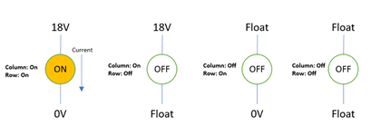
I don't know which machine you are referring to but I'll use a Williams WPC based machine as an example. These machines use an 18V supply across the bulb. This is because the bulb is 'strobed' as part of a lamp matrix. As a result, it is only driven ON by the power driver board for a maximum of 2ms in a 16ms period. This means it can only be driven ON 12.5% of the time - it will be OFF for 87.5% of the time. This means that it will only ever achieve a fraction of its expected brightness. To get around this, Williams used 6V bulbs but overdrove them at 18V to make them appear brighter - even though they are only driven for 12.5% of the time.
What does this mean for LEDs? I previously mentioned that LEDs need a current limiting resistor inline to ensure the LED doesn't draw too much current, overheat and die. If you put a 6V rated LED in there, it will be overdriven by an 18V supply - meaning it will take too much current. They have current limiting resistors built in to them but (IMHO), this isn't done correctly. Let's look at some measurements I took from bulbs and replacement LEDs.
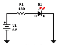
A 'standard' pinball machine playfield bulb is rated at 6V. When connected to a 6V power supply, it takes 240mA. If I take a replacement LED and connect it to the same 6V supply, it draws 30mA. This is where people think that LEDs as a drop in replacement means less power consumption - this is not the case.
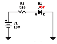
Remember I said that Williams overdrive the bulbs at 18V instead of 6V? Well, if I overdrive the LEDs using 18V, they take 207mA - nearly 7 times what we expect (and not far short of the amount of power a bulb would take).
The reason I mention this is that there may well be more than meets the eye when replacing playfield bulbs with LEDs.
I hope this helps with your original question. If not, please let me know and I'll do my best to help.
if you cant find the data sheet for your leds, connect your led to a 2-3.5v source (typical fwd voltage for most leds - if it doesn't light or is dim, increase voltage a bit, decrease if too bright) and measure it's current draw with your DMM. Once you know the current draw you can calculate the resistor value for whatever higher voltage you want to use. Typical Led is 20mA current but some bright ones are 150mA, so affects the resistor calc quite a bit.Very comprehensive, and very interesting - is there a way to work out the forward voltage & current without the data sheets? The reason I ask is I am planning to omit a circuit & drive some LEDs directly under Arduino control (via a relay, not direct) & based on what you have said, I suspect it may be sensible to add a resistor in the circuit. There is a pic of the circuit that I will not be using in this thread https://www.pinballinfo.com/community/threads/building-a-topper.52422/ - can't make out what that resistor is, but I may just re-use it.
Its a Firepower but I believe all Williams Sys 3 to 7 handle this circuitry in the same way.Hi Andy,
Thanks for this. I'm at work at the moment but I hope to get onto this and type one of my (typically) long replies in the morning.
Can you tell me what machine you are talking about so I can look at the schematics and offer a better answer to your question (a link to the schematics would be grand)?
Hi mate. Drop me a PM and we can chat about this one. I suspect there are many ways of doing this - I can hopefully point you in the direction of an easy (and cheap) way.Very comprehensive, and very interesting - is there a way to work out the forward voltage & current without the data sheets? The reason I ask is I am planning to omit a circuit & drive some LEDs directly under Arduino control (via a relay, not direct) & based on what you have said, I suspect it may be sensible to add a resistor in the circuit. There is a pic of the circuit that I will not be using in this thread https://www.pinballinfo.com/community/threads/building-a-topper.52422/ - can't make out what that resistor is, but I may just re-use it.
Thanks for pointing me in the right direction - what an excellent web site. This was just what I needed – clear schematics. Well done and all credit to the authors.Its a Firepower but I believe all Williams Sys 3 to 7 handle this circuitry in the same way.
An excellent resource for schematics is www.firepowerpinball.com with many thanks to Richard Harvey and Phil Butcher.


Hi Alan - I've made the measurements (across a set of 3 LEDs), but I'm not sure how to do the calculation. The measurements areif you cant find the data sheet for your leds, connect your led to a 2-3.5v source (typical fwd voltage for most leds - if it doesn't light or is dim, increase voltage a bit, decrease if too bright) and measure it's current draw with your DMM. Once you know the current draw you can calculate the resistor value for whatever higher voltage you want to use. Typical Led is 20mA current but some bright ones are 150mA, so affects the resistor calc quite a bit.
when you say “3 leds” i guess you mean 3 in series with each other? If so voltages you used seem to make sense.Hi Alan - I've made the measurements (across a set of 3 LEDs), but I'm not sure how to do the calculation. The measurements are
7.5V - very dim
9V - 10.6mA
10.5V - 27.6mA
12V - 46.4mA
Using V = IR doesn't give a consistent value for R across these three readings. However, by playing with the numbers [ie (V-x) = IR] using the first two gives a value for x roughly equal to 8, and substituting in the third keeps it pretty much the same. Unfortunately I don't know if this is a useful figure or just an artefact of the numbers.
How do I use these figures to decide on the size of resistor I need (or if I need one at all) - does it make a difference that I'll have 4 sets of the 3 LEDs in parallel
Cheers Alan - yes, 3 in series - still not sure what to enter for the forward voltage/current from the measurements I have taken.when you say “3 leds” i guess you mean 3 in series with each other? If so voltages you used seem to make sense.
If 3 in series were dim at 7.5v then their fwd voltage is greater than 2.5v each, you didn't say which of the other voltages gave the best brightness? If there was no real difference in brightness between 9v and 10.5v and 12v, then use the lower (as the higher will be overdriving the LEDS, resulting in a shorter working life), but also its possible to sometimes drive leds really bright - but this is also overdriving them and will result in a shorter life too.Hi Alan - I've made the measurements (across a set of 3 LEDs), but I'm not sure how to do the calculation. The measurements are
7.5V - very dim
9V - 10.6mA
10.5V - 27.6mA
12V - 46.4mA
Using V = IR doesn't give a consistent value for R across these three readings. However, by playing with the numbers [ie (V-x) = IR] using the first two gives a value for x roughly equal to 8, and substituting in the third keeps it pretty much the same. Unfortunately I don't know if this is a useful figure or just an artefact of the numbers.
How do I use these figures to decide on the size of resistor I need (or if I need one at all) - does it make a difference that I'll have 4 sets of the 3 LEDs in parallel
Thanks Alan, so roughly speaking, the forward voltage is the voltage the leds need to work, and the forward current is the current they carry when run at that voltage, & I'm calculating the value of the resistor that will limit the current to that value when running at higher voltages?If 3 in series were dim at 7.5v then their fwd voltage is greater than 2.5v each, you didn't say which of the other voltages gave the best brightness? If there was no real difference in brightness between 9v and 10.5v and 12v, then use the lower (as the higher will be overdriving the LEDS, resulting in a shorter working life), but also its possible to sometimes drive leds really bright - but this is also overdriving them and will result in a shorter life too.
Looking at the current draw, it looks like around 9.5v is what you should be looking at. Lets say with 9.5v, your 3 leds draw 18mA current. You decide you are powering with a 12v source. So:
Supply voltage = 12v
Forward voltage (desired voltage) = 9.5v
current 18mA = 0.018A
Desired voltage drop = 12 - 9.5 = 2.5v
Resistance = V/I = 2.5 / 0.018 = 139 Ohms.
