What's new
Pinball info

Register a free account today to become a member! Once signed in, you'll be able to participate on this site by adding your own topics and posts, as well as connect with other members through your own private inbox!

In Progress Rocky & Bullwinkle Shop Log

Thanks Rudi.

Good point on the coil sleeves - i'll get in touch with Andy and get some ordered in. When they arrive it's not a massive job to drop the end stop and swap the old one out. :-)

I'll look at trying PETG too. Plenty of people supplying it on eBay and it's not especially expensive so I can afford to have a few trys with different materials to see which works out best.
 
I've found a few more busted plastics that appear to be unobtanium (ball shooter cover is one). So i'm going to have a go at reproducing those too.

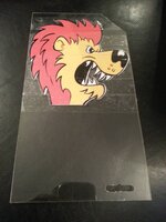
Here's my finished Lion art work. During the process of converting it to vector I managed to also clear out some scratches and blemishes from the original. Now just need to wait for the raw materials to arrive so I can have a go at fashioning the right shape.

LionPlastic_Final.png
 
Well in case you'd not figured it out i'm leaving that til last because that's going to be the hard part. ;)

A few ideas I have:

1. Speak to the people who do our signage at work. It may be that they could make the whole thing for me as the materials and processes used are almost identical.

2. Print the above design at the appropriate size onto acetate and then use a scalpel to cut it out. Then find an adhesive that could bond it to the perspex or PETG. Tricky part there I guess is finding an adhesive which won't cloud the materials.

3. Print the design onto gloss paper and then cut out with a scalpel. Stick this onto the rear of the PETG or perspex using appropriately adhesive.

4. Speak to a Company like The Plastic People to see if they could print directly onto PETG for me. This could be an expensive option but I guess there's no harm in asking. http://www.theplasticpeople.co.uk/

But first plan is to get the raw material formed to the right size and shape and then work on how to get the image there. Any other ideas of course are welcomed :D
 
I used this website to do it: http://vectormagic.com/home

The problem with scanned images is that solid colours generally end up looking like several different colours. The above website not only vectorised the image but it also filtered the colour palette down to just the 4 primary colours used - brown, yellow, black and white.

Quite pleased with how it came out. Just loaded into GIMP and then touched up a few areas. I've just noticed theres some colour bleed on the left so I need to go back and paint that out. But yeah, i'm quite pleased with that.

If I can find a good method of recreating the plastic I may well do the others as well so i've got spares.
 
Thanks. :-)

It does mention the method he used, although in this case it's a little different as the majority of the plastic is transparent so it looks like Rocky is actually pulling the lion from the hat. But that article will be really handle because there are a few other plastics I probably wont be able to source.

I'll be sure to keep this thread up to date with the latest developments. :-)
 
Thanks - i've dropped him a line.

Seems there's a lot of places online who can print onto self-adhesive vinyl. Might be an option for the Lion plastic.

Could also be a good way to get the cabinet back in good shape too. A hand-held scanner and some work in photoshop might allow me to isolate the elements and remove the background colour. Then print onto a transparent vinyl. Would mean I could then repair the damage to the cabinet, sand and then do a full respray in black before applying the vinyl.

Hmmm, I wonder just how expensive it would be to get the printing done......
 
Found a really interesting article on re-decaling a cabinet using water slides or vinyl: http://pinballrehab.com/1-articles/...binet/193-restoring-cabinet-graphics-overview

As a result of that article I found this which I think might be ideal for doing the Lion Plastic: http://www.amazon.co.uk/Inkjet-Creative-Vinyl-Stickers-Sheets/dp/B001W9LJ94/

Simply print the artwork onto one of those and trim the outline using a scalpel. Remove the backing and stick onto the Perspex/PETG form that i'll make.

That first article makes me think that a full cabinet strip and respray might actually be do-able after all. One issue I have to address is that the bottom of the artwork uses a moire pattern which is going to be an absolute biatch to recreate.
 
Fixed another minor issue tonight.

I'd played a few games and found that the ball was sometimes getting stuck behind the gate on the left ramp. Closer inspection showed that the left side of the gate was missing a nut and this means that with a few good whacks the gate would lift and the screw head would then cause it to jam.

It was a bit fiddly but I managed to stick a spare nut on there and it's working fine now.

I'm currently working to try to get the Nell Log Motor working. It's brand new but despite seeing a current at the motor connection point it's not moving. Not sure if there's something wrong with it or if it's something else. Russ Myers over at Pinside is helping me out, but if anyone here has any clues i'd be grateful to hear them. The relay is working just fine as you hear it click on and off when you do the Saw Motor Coil test.

I've located a reseller online that sells a 2" mecano pulley wheel which is probably a better fit than the 1.5" one i've already got. Should make the belt the right tension. Still no luck on the torsion spring yet but waiting to hear back from my contact.

Worst case i've found a job lot on eBay for about £5. I might well just take a punt on those and see if I can pick one that works for me. No rush right now as it's pointless until i've got the motor working.

Perspex should arrive tomorrow so I can at least check the width. I've gone for 1.5mm which I hope will be a match to the existing plastic. When i've got the right thickness I can do a trial run and possibly look at ordering some PETG for comparison.
 
The sheet of perspex I ordered arrived today. The good news is that 1.5mm is the perfect thickness, but as Rudi commented it's true to Perspex is much more brittle than PETG. In fact I did a couple of test cuts with my jigsaw and the very first one caused a crack to appear. Not good.

I used the Rocky plastic as a rough template and then overlaid my existing Lion over to top to modify it as required. The Lion has a straight bottom edge but the top right corner is clipped. Once i'd drawn the outline I very very carefully used the jigsaw to cut it to shape. Thankfully I managed to cut it without any major damage but i'm pretty sure the constant up and down is going to give it some severe hammer and it's most likely going to break eventually. No problems - it's just to prove the principal and i'll grab some 1.5mm PETG in the next week or two.

I then took my art work and printed it onto an acetate sheet before overlaying that on plain paper and carefully cutting out the image. It was a total pain in the **** trying to cut it out using scissors and the result is a bit rough around the edges. I'm going to invest in some scalpels I think for the next attempt.

Once i'd done that I used some selotape (yup, selotape) to fasten the image onto the perspex. It's obviously far from ideal but again it was only done as a test run. A few things i've learnt from this:

1. Use PETG not Perspex.
2. The colours for the printed Lion were out so I need to print a colour swatch and try to match the colours better. The main Lion was pretty close but the mane was more red than brown.
3. Get some scalpels to cut out the decal once printed.
4. Use a different material. One option is to print is as a water slide and transfer it over, but i'm leaning more towards adhesive backed vinyl like this: http://www.ebay.co.uk/itm/WHITE-A4-...nter_Paper_Accessories_ET&hash=item1e70b6b67a
5. The sides of the PETG need to be finished with something (wet/dry maybe?) to give them a nice smooth finish. If anyone knows what is best to use here i'd love to hear more.

But on the whole I think the final result is a good start. At least I have something I can trial and i've learn some valuable lessons for the next run. I have considered using a company to print the decal as a Window Sticker but the issue I have with that is that it'll cost around £10 per print that I do so until i'm certain on colour registration and image dimensions then i'm a little reluctant to go that route. Possibly something for me to consider at a later date when i've got a little more ready money to spend.
2013-06-25 20.17.46.jpg

And reinstalled back in the machine.

2013-06-25 20.20.34.jpg

And finally a short video showing it running in test mode. Quite happy with my first crack at it - i'll probably grab the other bits I need in a week or twos time and give it another go. In the meantime I can test the durability of the perspex one i've made and it's a darn site better than having no Lion at all.


Also, note that Rocky seems a little reluctant to go back into the hat. I need to take a look at that and figure out what's going on. Could just be the plunger needs cleaning and the sleeves replacing. And finally apologies to anyone blinded by the stupidly bright flickering LEDs in that backlight. They were only installed as a test but they're definately not the right ones to be using there and they won't be staying.
 
It is really impressive to see you get stuck in with this. I tinker with my machine, solder and fix things but have not yet come close to making a missing part like this. You are learning and moving forward so good luck with the next attempts.
 
Thanks Calimori.

I have to say the enthusiasm and helpful nature of people on this forum is a massive help and something of an inspiration. It's great fun to do this kind of work on the table, but even more so when I have family and friends round and they all get a blast from having a few games. My 3 year old grandson is already hooked on Pinball, which is going to be great justification for more tables in the future. ;)
 
Couple more small jobs tonight - was going to give it a miss but I heard the table calling me. ;)

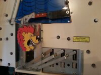
The Rocky plastic now drops back down correctly. There was something sticky on the pivot point of the metal arm that raised the plastic so I stripped that and the coil. Cleaned the plunger, replaced the coil sleeve and cleaned the pivot point. Tested and working fine again now. :-)

Also replaced a blown bulb in the start button. Used one of my old #555 for now but will eventually change it for a LED. At least it's another job off the list for now.

Loving this. Even small jobs are really satisfying. :-)
 
Well, thanks to the kind souls on this forum I finally got to the bottom of my 'multimeter not reading volt measurements when using the ground braid for earth' issue.

The downside is that it's made a few more jobs for me. Although, i'm not sure it really is a downside as i'm finding it good fun.

So, jobs that go on the list are.

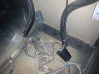
1. Remove the ground braid that is just loosely trailed over the bottom of the cab and install a new segment from the left rear to the right rear of the cabinet, securing it to the back as we go. Also install a short run from the back bottom to the backbox so we have continuity throughout.

2013-06-27 16.39.02.jpg

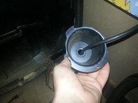
2. Cut a hole in the back of the cabinet and fit a new cord cup, routing the cable correctly as we go. Erm, the old one is a little broken.

2013-06-27 19.56.31.jpg

3. I'm also contemplating changing the leg bracket at the right rear of the cab so it matches the other side. A little OCD maybe but that corner is the badly chewed area so anything I can do to reinforce things can only be a good thing.

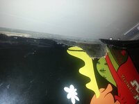
I've not shown it yet so here's the extent of the damage to the back corner of the cab. As Matt put it 'it appears to have been attacked by a shark'.

20130627_164553.jpg

I think the plan is going to be to strip off the head and remove the playfield before removing the legs and taking the main cabinet outside. Whilst i've got it that way I might as well give it a damned good clean both inside and out before doing the ground braid and new cord cup. At the same time i'll fill that chewed area of the cabinet with epoxy. Still not sure what i'm going to do about the cabinet art just yet - there's a few areas which need some work but I think in general it's in pretty good shape. It would be a shame to spend a lot of time and effort creating vinyl decals if it means covering up original artwork which is in relatively good condition.

I think therefore i'll fill the holes and carefully sand them back for now and do a more detailed appraisal of what areas need touching up before making a decision. Areas of solid colour should be relatively easy to handle but there are some areas where a moire pattern is used and that's going to be extremely hard to work with.
 
Regarding the motor it could be the wrong type, just coz it looks new doesn't mean it's the correct one. However you could possibly make it work for you. I'd disconnect it from the game and try a separate power supply on it to see how it works. I'm guessing it probably needs more than a two volt drop than what you have seen, I'd expect at least 5v then you might see the motor move. If that is the case then you could add a big resistor to help pull down the difference and have a working motor...

I hope you managed to understand all that...! :)
 
The table was owned by Dan previously and he picked up the motor and was trying to get the whole assembly working.

Of course it's totally possible it was DOA, but as you say the only way to really prove this (or not) is to get a proper 24v supply to test it on.

Not managed to locate one yet and was a bit reluctant to buy one just for the sake of testing the motor.

The one i've got looks exactly the same as this: http://www.marcospecialties.com/pinball-parts/041-5023-00
 
Had a lot of family stuff on this weekend so not much time for pinball repair, although I did manage to grab a few games with the wife and the kids. Good fun :)

Only repair was I had to do a temporary fix on one of the flipper return springs. The end hook holding it in place snapped off causing the flipper to stick in the up position. I used some needle-nose pliers to make a new hook point so at least it's working for now.

Spare flipper return springs are now on my list of items to put an order in for.
 
Tonight I removed a couple of bulb holders for the GI. I'd fitted new LEDs a week or three back but the sockets were recessed into the area near the Nell Log Assembly so getting them to make a good connection was a PITA. So tonight I disconnected the bulb holders and installed the LEDs properly before putting it all back together. Hopefully not a job i'll have to do regularly.

I've also taken another look at the Saw Motor wiring and it's still making my head hurt.

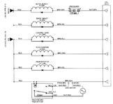
Here's the diagram from the manual.

SawWiring.png

The section of interest is at the bottom and if i'm reading it correctly we have the following going to the relay board:

From Power Supply Connector #3 Pins 6/7 we have +32 VDC (Red)
From CPU Board Connector #12 Pin 1 we have 28 VAC (BRN-BLK)

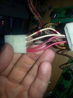
You can see the above going into a molex like this:

2013-06-23 19.44.14.jpg

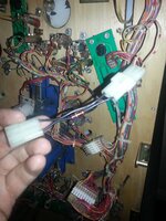
On the above molex the white and white/red cables go to the saw motor itself. It then also passes through a special small cable which appears to have a 65 ohm resistor built into one side of it.

2013-06-23 19.42.30.jpg

Now if my memory of electronics from school is correct the concept with the relay is that constant current is supplied to it but then a further current is used to energise (or not) an electro-magnet that will either close or open the gate, thus allowing current to flow or not. In the above diagram we have two currents, one at 32vDC and the other at 28VAC. The diagram suggests that the motor needs the AC current applying to it, but what is strange is that when I measure the voltages involved I see massive differences to what i'd expect.

The 32VDC is reported as 41V+ when measured and the AC current is showing at over 60V.

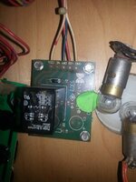
Another quandry I have relates to the Relay board. The wiring diagram suggests white/red should be wired to GND on the relay board but on mine white/red is connected to COIL whilst White goes to GND. There's no mention of just a white cable in the schematic.

2013-06-23 19.41.12.jpg

If anyone has any clues or advice on how to trouble-shoot this step by step i'd really be grateful. It's been years since I did my education in electronics and i'm struggling picking it up again.

Thanks

Pete
 
Brown-black feeds to red through coil in relay that activates the relay. Feed for the motor 28VAC from br2 through the relay is red-white onto the white wire to one side of the motor and another red-white wire on the other side of the motor back to br2.

I'd reflow the wires and relay connections on the relay PCB to remove any possible hairline cracks.

Regarding the white only wire it should be red-white according to the drawing but they probably ran out of red-white at the factory.
 
Also suggest following br2 and check the motor is 28vac. Measure with probes across the motor to see actual W3C value when motor is suppose to be running.
 
BR2 = Bridge Rectifier 2?

I have to admit I don't know why but I sat wondering for ages what the feck BR2 meant, and then it came to me in a blinding flash. It should have been obvious.

What's W3C though?

Thanks for the suggestions so far. I'll give it a go and report back.

Pete
 
The solder joints on the relay board looked in good order but I reflowed them anyway to be on the safe side.

Measuring the power at the saw motor connector I get 0VAC at idle (as expected) and 29VAC when the coil is pulsed in the test menu. That should be ample to drive the 24VAC motor.

The motor does absolutely nothing so i'm assuming it's deaded. Time to add a new one to my list of stuff to buy.
 
I very nearly bought this machine but my arms were just a touch too short for my pockets.

Looks like its in good hands now. That lion artwork came out very well.
 
Back
Top Bottom