What's new
Pinball info

Register a free account today to become a member! Once signed in, you'll be able to participate on this site by adding your own topics and posts, as well as connect with other members through your own private inbox!

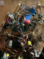
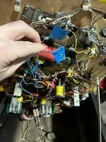
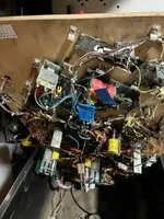
Pictures of BK 2000 underside of the play field

GrizzlyNate

Registered
Joined
Dec 15, 2024
Messages
28
Location
Texas
I have a BK 2000 I am working to restore. I have worked on the mpu to get the pin to boot up. I have a ton of relay switches not reading though and both the right flippers not working. When I look under the play field I can tell one of the lamp relay boards is missing so working to replace it. However, I have a green with reddish purple stripes not connected to something and a white and black wire as well. I have figured out one of the green purple is the connection to the rest of the switches I think to the right side but something is missing that they all should be connected too. I also have a switch just dangling and can not figure out where it goes. I am just asking for some underside pictures of the front of the play field to figure out where these wires connect so I can fix that and then start addressing why certain switches are not working. I know the start button switch as well is not registering so this lets me know I have other issues but got to get it all connect first to start tracking it down.
 

Attachments

  • IMG_5171.webp
    IMG_5171.webp
    119.3 KB · Views: 21
  • IMG_5170.webp
    IMG_5170.webp
    77.9 KB · Views: 21
  • IMG_5169.webp
    IMG_5169.webp
    100 KB · Views: 21
Hello, Nate,

The serious-looking switch you have simply dangling belongs on the right-hand flipper; the plastic triangle bears on the flippers' regular End-of-Stroke switch, so that the flipper linkage pushes open the EoS as intended, and also closes the additional switch to operate the upper flipper. Williams often/usually switched extra flippers from the button switch(es), but Black Knight 2000 was an exception. The flipper assembly may have lost the longer screws needed to fix the two switches, unless they've been fitted regardless, and damaged the coil..

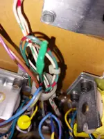
The U.K. allocation of this game didn't have a playfield tilt switch, but the wiring was provided. I see two Green-red wires loose, I'd join them together to have continuity for that switch line, Column 2, which also serves the outhole and ball trough switches. Having those not showing would prevent starting a game, though I'd half expect a display message about balls missing.
 
Last edited:
That explains why my bk2k came without the playfield tilt switch. It's the same on yours Nate. From the switch matrix the plafield tilt is switch 9 and is green/red and white/brown wires. So just tape the ends of those two up separately and tuck them in the wiring loom.

Edit for clarity As Jay Walker states tape the green and red wires together for continuity but keep the white/brown wire separately taped.
 
Last edited:
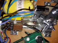
Pics of isolated switch wires - >I always use heat shrink rather than tape for a neater finish. Plus also what the right flipper switch stack should look like. The manual only lists the shorter screws as #5 5/8". It doesn't list the longer ones which are needed. If you don't have the longer screws just add the height of the second switch that is dangling to the 5/8"
 

Attachments

  • 20241221_103508.webp
    20241221_103508.webp
    87.9 KB · Views: 15
  • 20241221_103342.webp
    20241221_103342.webp
    193.7 KB · Views: 15
  • 20241221_103418.webp
    20241221_103418.webp
    64.1 KB · Views: 15
Asia and Jay,

Thank you both for the input. I will be getting those wires and the flipper switch fix tomorrow. I’ll try to start the game again and see what I have. Maybe back as to understand if certain switches are still not showing as being activated. The other thing is from the person I got it fro
Said the right flipper did it work. Not sure if that was too flipper or both. I know right now when I click the flipper button it does not fire. Once all in place I’ll get some v measurements as I have leaned it’s best to start there. I did a trace on the wires and they do go back to the mpu and power board for continuity but that just lets me know wires are connected.

Aisa is it hard to convert the springs? This is something I might look at down the road.
 
Back
Top Bottom