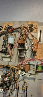
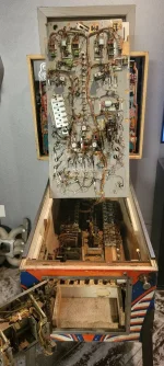
Hello everyone, Just bought a Capt Fantastic Machine. Wanted one since I was a kid. It's a fixer upper but got a good price. It mostly works and I have been tinkering and figuring out what's what. It is currently set up for free play altough at some point I may try to tackle the coin op part. My first question is in th eupper right corner of the back of the palyfield is a missing relay solenoid. Can someone tell me what this is for and where I can get one?
Pinball info
You are using an out of date browser. It may not display this or other websites correctly.
You should upgrade or use an alternative browser.
You should upgrade or use an alternative browser.
New to the hobby and looking for help on Capt Fantastic machine
- Thread starter Wade
- Start date
I would start by looking at the schematics and user manual to try figure out what it’s for.
 www.ipdb.org
The Internet Pinball Machine Database
Hello, Wade,
You foxed me at first, by saying 'upper right corner', but with the playfield raised. I wondered about the close-up.
With that missing relay, I don't really see the harm in pushing the frame, so that the contacts attached make and break as they would if the relay was present. Just be watchful of whatever effect this may have.
I see looking closer that there's a fragment of the relay frame still attached, the wire colours may help to see what it is. Red would be the shared supply to most relays, the other wire should help to identify the relay.
Last edited:
Look it up in the manualThanks for the responses. Jay there is a red wire as you suggested and the other wire is white or gray with wide dark blue or purple rings like a snake.
Do you have sight of the schematic diagram? It's a scary thing to look at, but I notice that the Red power wire, labelled 10 (Red with no tracer) originates at the 'Bridge Rectifier', towards the right in the lower half of the diagram, and is fed to playfield solenoids and relays, then changes to Red-white, 15, upon reaching contacts at the Tilt relay. So if that is the Red wire on the fragment, we can follow it through the diagram, where it moves along to the right then U-turns to reach the upper half of the drawing.
Looking at each device it's connected to, I don't see a Grey-blue wire used, but a couple of Grey-black. One is 'Alternator relay', the other 'Targets Sequence No.1'. Another look at your close-up picture shows a paper label caught in the wiring near the vacant relay mounting; I may be able to guess at the lettering 'Alternator Relay' on it. This may have detached from the relay bracket in an overheating situation that destroyed the relay.
Both of the two uses listed use the same relay winding, a G-32-2500.
The alternator relay is used to switch the top inlanes, either the centre one is lit or the 2 sides ones are lit. These should alternate every 10 points score that is made. So should be easy to test if you start a game and see if they alternate or not - if not - as @Jay Walker suggestes above, try manually operating the switchesDo you have sight of the schematic diagram? It's a scary thing to look at, but I notice that the Red power wire, labelled 10 (Red with no tracer) originates at the 'Bridge Rectifier', towards the right in the lower half of the diagram, and is fed to playfield solenoids and relays, then changes to Red-white, 15, upon reaching contacts at the Tilt relay. So if that is the Red wire on the fragment, we can follow it through the diagram, where it moves along to the right then U-turns to reach the upper half of the drawing.
Looking at each device it's connected to, I don't see a Grey-blue wire used, but a couple of Grey-black. One is 'Alternator relay', the other 'Targets Sequence No.1'. Another look at your close-up picture shows a paper label caught in the wiring near the vacant relay mounting; I may be able to guess at the lettering 'Alternator Relay' on it. This may have detached from the relay bracket in an overheating situation that destroyed the relay.
Both of the two uses listed use the same relay winding, a G-32-2500.
As @AlanJ said above:
The alternator relay is used to switch the top inlanes, either the centre one is lit or the 2 sides ones are lit. These should alternate every 10 points score that is made. So should be easy to test if you start a game and see if they alternate or not - if not - as @Jay Walker suggestes above, try manually operating the switches
The alternator relay is used to switch the top inlanes, either the centre one is lit or the 2 sides ones are lit. These should alternate every 10 points score that is made. So should be easy to test if you start a game and see if they alternate or not - if not - as @Jay Walker suggestes above, try manually operating the switches
Again, the schematic is where to look for help with this. Unlike an electronic solid-state machine, where the software switches a transistor to pulse the solenoid, an electro-mechanical game has to contrive a circuit using various contacts, and the solenoid draws current for as long as the circuit remains 'made'. Find the knocker solenoid winding on the diagram, and look at how its circuit pathway is routed. Williams e/m games used to have the knocker switched by the credit/replay counter unit being advanced - the linkage which 'stepped' the counter upwards also closed contacts for the knocker solenoid.


