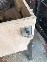
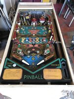
i think it’s cos: no coin door, no glass channel, no flipper buttons.
Pinball info
You are using an out of date browser. It may not display this or other websites correctly.
You should upgrade or use an alternative browser.
You should upgrade or use an alternative browser.
Complete Mishmash self build - let’s make a pinball machine
- Thread starter AlanJ
- Start date
Possibly both 
Thanks @myPinballs - I may need a lockdown receiver for the next one, but I've just sourced one for this project.
Looks odd.
Not a criticism, just saying.
I can't even put my finger on why... Think it's cos the sides don't look. Like a factory pin iyswim
I thought that on seeing a Fireball homeplay version in a film, and realising that a homeplay at the time wouldn't have had a coin door, just a lock to release the front moulding. Though for a Bally e/m, it would be the 'canopy' (front moulding, side rails and glass combined).
Last edited:
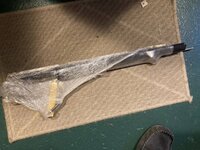
Lockdown receiver arrived today thanks to @paddythegreek . It’s getting the rust removal treatment for 24hrs.
The plastic glass channels are expensive so opted for a cheaper version using U channel and a sliver of wood to hold it in place.
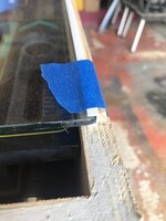
The plastic glass channels are expensive so opted for a cheaper version using U channel and a sliver of wood to hold it in place.

Was supposed to spend today on the controller board which i designed and had made several weeks ago. I had 5 prototype pcbs made and for the life of me i can’t remember where i put them. doesn’t help that we had a big tidy up at home for my 60th birthday bash. I’ve wasted a couple of hours today looking for the blooming things. I’m the end i’ve just ordered another set of 5 from the manufacturer. if i find the others in the meantime i can crack on.
If i cant find them it’s a 2-3 week wait for the new ones, so i’ll get on with installing a set of addressable rgb leds into the playfield. that will allow me to test out my new playfield rotisserie.

If i cant find them it’s a 2-3 week wait for the new ones, so i’ll get on with installing a set of addressable rgb leds into the playfield. that will allow me to test out my new playfield rotisserie.
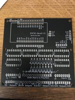
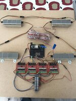
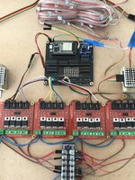
mpu board built and populated.
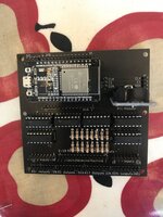
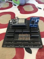
The board had the cpu board (esp32s) which had built in wifi, ive got 16 inputs and 32 output ports. Then there is a real time clock board with backup battery. as well as the inputs and output headers there are headers for: the lighting and the score displays.
Next I think I’ll build a simple board and place this and all the score displays plus the power boards for the solenoids……
Ashbo
Site Supporter
Between you and this guy, I'm talking myself into moving house to somewhere with a workshop!!mpu board built and populated.
View attachment 149550
View attachment 149551
The board had the cpu board (esp32s) which had built in wifi, ive got 16 inputs and 32 output ports. Then there is a real time clock board with backup battery. as well as the inputs and output headers there are headers for: the lighting and the score displays.
Next I think I’ll build a simple board and place this and all the score displays plus the power boards for the solenoids……
Where did you get your PCBs printed?
you don’t need a workshop, just take over the house like me!Between you and this guy, I'm talking myself into moving house to somewhere with a workshop!!
Where did you get your PCBs printed?
pcbs i use jlcpcb in china
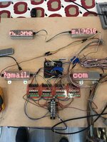
So i’ve laid out a basic “backbox” on a mdf board approx 64cm x60. so smaller than a typical bally ss insert. this is not intended to be the final layout (but it might be ), rather just a working board where i can secure all the components. so mpu board in the middle. 4 dot matrix (single colour) score displays. (i may add another in future for the usual thing of ball in play/credits/match). the reason i haven’t added it is because i don’t need credits or match, and i think i can use the player score displays to show the ball in play as well.
At the bottom are 4 x 4 channel mosfet drivers, giving me 16 solenoid outputs.
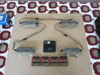
At the bottom are 4 x 4 channel mosfet drivers, giving me 16 solenoid outputs.

Ashbo
Site Supporter
Just challenging my understanding, the mofsets allow you control board to fire off low current signals that initiate a high current circuit?4 dot matrix (single colour) score displays.
View attachment 149579
Are the dot matrix displays operated like addressable LEDs?
Ashbo
Site Supporter
Cheersyou don’t need a workshop, just take over the house like me!
pcbs i use jlcpcb in china
Call me a pessimist - but is 16 inputs enough ?
I guess with it setup that way you can plug the board straight into your PC/Laptop/Whatever and program it and test "on the fly" as it were ?
I guess with it setup that way you can plug the board straight into your PC/Laptop/Whatever and program it and test "on the fly" as it were ?
Yes, the mosfter boards, take a low level signal out of the processor and then allow you to switch on and off a higher voltage & higher current load, suck as a pinball solenoid.Just challenging my understanding, the mofsets allow you control board to fire off low current signals that initiate a high current circuit?
Are the dot matrix displays operated like addressable LEDs?
The dot matrix displays are not addressable LEDS, they use a MAX7219 chip which has a different set of commands compared to addressable leds.
16 inputs becomes 64 when you matrix them into an 8 X 8 switch matrix, so yes, plenty of inputs.Call me a pessimist - but is 16 inputs enough ?
I guess with it setup that way you can plug the board straight into your PC/Laptop/Whatever and program it and test "on the fly" as it were ?
Yes, I can do a lot of the softwware develpment now without having the playfield plugged in, but to be honest I'm just going to get the playfield on the bench as well soon anyway, as I need to wire in the new LED lighting to it.
That would certainly make things a lot simpler than the breadboard and its wires all over the place 
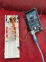
Just to fiddle around with some LED sequence stuff. (Obliviously I appreciate that's kinda what the breadboard is for but you get what I mean )
)
Does the ESP board just plug into the PCB - or is it soldered in ?

Just to fiddle around with some LED sequence stuff. (Obliviously I appreciate that's kinda what the breadboard is for but you get what I mean
Does the ESP board just plug into the PCB - or is it soldered in ?
Ive put sockets on the main board, and the ESP board plugs in - 2 reasons - I can then easily unplug the ESP and take it to my laptop to update the software, and secondly, if it fails, It's easily replaced.
Btw - during the software development, I will need to connect the laptop directly to the ESP board to update the software, but once I have finished the project, I will add in OTA - "Over The Air" software updates, so then I will be able to update the software from my laptop or phone...........A long way off that yet though.
Btw - during the software development, I will need to connect the laptop directly to the ESP board to update the software, but once I have finished the project, I will add in OTA - "Over The Air" software updates, so then I will be able to update the software from my laptop or phone...........A long way off that yet though.
PS - Looks like you are having fun there Bruce. Shift register???That would certainly make things a lot simpler than the breadboard and its wires all over the place
View attachment 149580
Just to fiddle around with some LED sequence stuff. (Obliviously I appreciate that's kinda what the breadboard is for but you get what I mean)
Does the ESP board just plug into the PCB - or is it soldered in ?
Consider making OTA a priority... This will save you a lot of time during development. There are existing esp32 ota implementations that you should be able to drop in.Btw - during the software development, I will need to connect the laptop directly to the ESP board to update the software, but once I have finished the project, I will add in OTA - "Over The Air" software updates, so then I will be able to update the software from my laptop or phone...........A long way off that yet though.
I’ve got it in my dev framework already so i can use it from the get go, but as this thing is going to be on the bench for a long time it’s actually easier to just plug into the laptop.Consider making OTA a priority... This will save you a lot of time during development. There are existing esp32 ota implementations that you should be able to drop in.
Today I’m going to do a bit of coding. First job is to grab the code I originally wrote to read the playfield switch matrix and test with the new mpu board and see what happens.
Also, when I fired up the power last night I saw that several of the solenoid outputs were coming on at random. Those need to be all off for sure at startup, so I’ll look at that too.
Also, when I fired up the power last night I saw that several of the solenoid outputs were coming on at random. Those need to be all off for sure at startup, so I’ll look at that too.
Here’s a video of the switch matrix testing:
It all works fine. next i’m going to get the score displays working
It all works fine. next i’m going to get the score displays working
4 dot matrix (single colour) score displays. (i may add another in future for the usual thing of ball in play/credits/match). the reason i haven’t added it is because i don’t need credits or match, and i think i can use the player score displays to show the ball in play as well.
And why not, with dot matrix displays? It didn't take the manufacturers long* to save on the cost of the 'Status' display, as I think Williams called it; once alpha-numeric/starburst displays came in, only a few more games had a Credit/Ball in Play display. From F-14 onwards, Ball in Play showed in player 4 display, unless there were 4 players, when it alternated with the score of the player currently 'up'.
The pre-merger Bally Midway did away with it immediately, placing their alpha-numeric displays along the bottom edge of the backglass
Last edited:
https://youtube.com/shorts/c-***HGvsE8?feature=share
Last edited:

