What's new
Pinball info

Register a free account today to become a member! Once signed in, you'll be able to participate on this site by adding your own topics and posts, as well as connect with other members through your own private inbox!

Complete Mishmash self build - let’s make a pinball machine

I must be fricking mad.
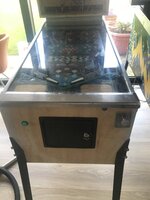
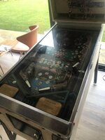
I bought this fully populated playfield a couple of years ago. It was going to be a wall art led project, but it’s fully populated, so it’s almost a pinball machine, right? It needs to be saved and turned back into a fully working game again, right?
View attachment 142802
View attachment 142803
View attachment 142804
View attachment 142805
View attachment 142806
It’s absolutely filthy (it arrived to me like that).
It came from @BrianSoton if I remember correctly.

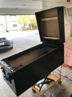
So first job is it needs a cab. I’ve found one courtesy of @MartinY - which is getting picked up by Martin (retro logistics) on Monday, so should arrive to me later in week I hope.

So I got a pf and a cab. I’ve got legs and a shooter rod. What else? Well, this is where it’s going to get interesting……

The real jist of this project is for me to tread in the footsteps of all those amazing people who have designed and built pinball machines. I want to have a go at building the rest of the machine from scratch, using my own ideas and designs, using std off the shelf electronics, parts, boards, etc. I want to pick a mpu processor and do all the programming myself.
Like I started off saying. I must be mad……😂

So i’m going to need:
power supplies
cpu/mpu
light controller
Switch input reader
solenoid drivers
score display
software
+loads of other stuff i haven’t even thought of

Why?
1. Just for the hell of it. So I can (almost say), hey i designed and built a pinball machine.
2. So I experience first hand (some of) the challenges and issues that pinball nanufacturers have.
3. To bring back to life a playfield into a fully working machine, hits my recycle/reuse ethos very nicely.


Ok so yes I know I have cut a huge corner by using an existing pf, but it’s beyond me at present to aim to create a whole new machine from scratch. Maybe later, if this one works out.

I’m also intrigued about time and cost.

The pf is clearly below real cost. I think I paid £125 for it (I bought it in a job lot with other stuff).
The cab plus delivery £150.

I’ll keep a record of time spent and parts and materials costs.

At this time my only though is use an ESP32s cpu because that is my area of knowledge.
Brian Soton has power supply
 
Well done Mate looks great - you will be forever tweaking it now :-) Will you be doing an LE version :-)

Nice one.

JB
 
Cheers @Biff Yes this is going to go on for as long as I want it to.

While testing I noticed some spurious switch triggers going on. Looks like its to do with my cabinet switch matrix wiring. So I tested all that out and checked it out, it is all wired correctly and diodes on the right way around and fully working???
When I unplug the cabinet switch matrix everything on the playfield works as it should, but as soon as I plug in the cabinet wiring, I get odd spurious results, seems to be only on row 7. That's the row I have connected the right flipper to, so it must be that wiring that is causing the issue. The rows are held low by pull down resistors, so should only be high if a switch is properly closed and the column of that switch is active - i.e. set high. The wire to the right flipper is the longest wire in the run of cabinet wiring, and so maybe it's picking up some interference somewhere??? Maybe I'll pull it to ground via a resistor at the switch end of the wire? My Flipper buttons have a LED inside them to illuminate the buttons, so Ive got an easily accessible ground connection right there in the flipper button.

Noticed some errors with the HSTD entry and a few other niggley bugs and timing issues. I'll fix those and also have a go at getting some lighting shows going in attract mode.

Since I swapped power supplies, I am also getting a trigger on the solenoids when first power on, this is a real no-no and so I need to figure out a way to sort this. I guess I should pull the MOSFTET driver inputs low with resistors, but also I could delay the solenoid power coming on until after the MPU has booted, as it quickly shuts the mosfets off anyway.
 
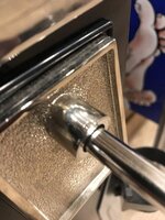
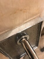
Decided to install the lockdown bar receiver today - what an error I made, I should have done this earlier in the project when the cabinet build was happening. There is a lot of things to get right at the front of the cabinet, the lockdown receiver needs to be just the right depth to receive the lockdown bar and lock, so not to deep, but also not too high either, otherwise the playfield sits too high. Ive had to mess around for a few hours to get the height of the plunger just right - needed to saw the hoe out in the front to make it sit higher up as it was catching the edge of the playfield. I also discovered the plunger is too short, I am using one off the longer ones, then realised its for 2 reasons - 8 ball champ has a built in plunger lane housing as part of the plastic apron and this sits further up than all the traditional bally SS shooter covers. Also I have used a Williams shooter housing which moves the plunger back about 2/503cm compared to a bally one. Im either going to extend the rod, or make a longer one, or somehow shorten the front barrel of the housing to move the plunger deeper into the cabinet....................

On the plus side I have sorted a load of other issues out. the cabinet switches are now working 100% and not causing any spurious switch triggers in the matrix - I grounded the right flipper wire to earth with a 15k resistor and that cured the issue.

Done a load of play testing and got quite a few niggles sorted out. Got some attract mode light shows going. More to do.

Ive got a chunk of coding to create a set-up menu where settings can be altered and diagnostics mode entered etc.
 
894CE8CA-4E7C-4D74-B631-78A735D7CCA5.jpeg
D3110291-0190-45F9-9416-834126297CB4.jpeg
I had to shorten the front of the shooter housing. the bottom pic is the shortened one. the top pic is one from my other machines because i forgot to take a “before” pic of the one i cut down. 😂😂. i was worried it would look rubbish and it may wobble side to side or up and down, but it all looks good and works good.
 
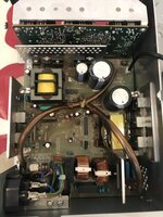
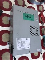
My new power supply turned up. looks good and tested out ok on the bench. will install it in the machine and see how it functions.
49DB8F6C-29BC-4FA1-88EB-DFA7287AE1A6.jpeg

3CF99C1F-B72C-47EB-AC12-ED29B86B7547.jpeg
 
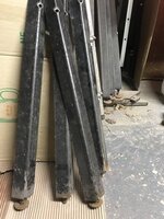
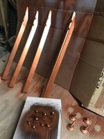
Legs need sorting. i put on some really knackered old things (that won’t even height adjust) to get it on its feet initially, but now it needs something thats better and so i can jack up the back end height
 
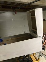
No recent progress on this - I painted the cab, tried some simple stencils but they didnt work out so well, so having a rethink. Really need to get the cab sorted so I can reassemble and crack on with the game code.
 
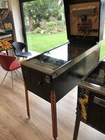
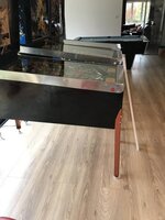
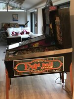
Cab is based in black paint awaiting stencils or decals. I’m going to go scan a cab and backbox in a couple of weeks time. Legs, side rails and lockdown bar all on. I decided to screw the side rails to the cab, rather than use the nails. I guess they were nailed originally for security reasons (screws could be easily unscrewed), but in a home environment, that’s no longer an issue.

FFB57AA9-A2AC-4A98-903E-B4AD6EAD881E.jpeg
DE1D84EB-2768-43B3-AFEF-EEE37A8477A2.jpeg
 
The new power supply isn’t up to the job. it kept cutting out, so i swapped back to the other two supplies, then i realised why. the lower right flipper eos switch stack has broken (the little white plastic spacer on the end of the leaf has dropped off - found it in the bottom of the cab), this caused the flipper to stay on full power, burning out the mosfet so keeping the lower right and the upper right flipper on all the time, which caused the psu to shut down via its protection circuit. Anyhow i’ve sorted the eos issue with a bit of a hack fix (a small rubber ring) as i can’t find an eos switch handy or one for sale. I guess i could now move back to the other power supply but first gotta sort the duff mosfet as well
 
The backbox on Cosmic Gunfight in the background there is looking somewhat unloved :D
It’s on the restore list. i’ve got the stencils. just need to get through a few other machines first. there is this mishmash project, plus started the goldball cabinet refurb, then your old Elektra, then either cosmic gunfight or stern meteor 😂😂😂
 
Can’t find The EOS switch stacks or even a spare switch blade in the uk, so decided to put in an order to Europe. I realised that i probably need a few spare sets of eos switches and some other bits and bats to make the postage worthwhile. Edit. as soon as i placed my order i found some on ebay uk. sod’s law 😂😂

I also had a look at the flipper coil specs. the initial flip coil is only 3.3 ohms and the secondary hold coil is 350 ohms. So by having a duff eos switch, then the unit is drawing over 13A. (44v / 3.3), so no wonder my power supply was cutting out! If the eos switch is working properly and the secondary coil switches in, then the power draw is 0.125A which is fine.
 
Last edited:
C1413B2A-5367-4E7C-B757-E1FB3E00D963.jpeg
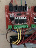
I thought these 4 way Mosfet boards were a good idea but they are a bit of a pain to swap out. it’s the 7 wires that screw into the screw terminals at the bottom. the screw terminals are crap quality and i’ve probably used wire that is too thick. it’s a real pain getting two wires into a single terminal. as with the brown +ve wire that i decided to daisy chain. In hindsight i should have wired each individually, so i may go back and redo that.

Anyhow Instead i cheated and did a nasty hack fix - snipped off the duff mosfet and soldered one directly onto the pins that were left.
 
View attachment 153271
I thought these 4 way Mosfet boards were a good idea but they are a bit of a pain to swap out. it’s the 7 wires that screw into the screw terminals at the bottom. the screw terminals are crap quality and i’ve probably used wire that is too thick. it’s a real pain getting two wires into a single terminal. as with the brown +ve wire that i decided to daisy chain. In hindsight i should have wired each individually, so i may go back and redo that.

Anyhow Instead i cheated and did a nasty hack fix - snipped off the duff mosfet and soldered one directly onto the pins that were left.

Those screw terminals will be 3.96 pitch. Just remove them with a solder sucker and replace with classic headers, then you can fry your mosfets to your hearts content! 💕
 
Those screw terminals will be 3.96 pitch. Just remove them with a solder sucker and replace with classic headers, then you can fry your mosfets to your hearts content! 💕
Unfortunately they arent - but I think in hindsight it would have been easier to make my own 16 way solenoid driver circuit. there isnt much to it - Opto isolator driving a mosftet, a few discrete components........... Maybe for V2 I'll do that.
 
Haven’t had time or motivation to work on this for a couple of months but decided to pick it up today

First job. i got some artwork printed. simple but better than nothing
D6A96999-C9EF-4B4C-B1D8-ED636F11D24A.jpeg

Been having an issue with solenoids firing on power on, so i’ve added a delay timer circuit which delays the power to the solenoids for a few seconds after power up. this gives the esp32s time to boot and switch all the power drivers off.

I’ve installed the speaker in the cab properly.

Started to make a frame and locking mech for the acrylic backglass.

I have new parts to rebuild the flippers

Need to rerubber the playfield.

Once i get all the hardware sorted i’ll get onto the software again. the game works fully but i can do so much more with it!!!!
 
Haven’t had time or motivation to work on this for a couple of months but decided to pick it up today

Been having an issue with solenoids firing on power on, so i’ve added a delay timer circuit which delays the power to the solenoids for a few seconds after power up. this gives the esp32s time to boot and switch all the power drivers off.

Motivation for these types of projects is hard especially after the initial excitement phase wears off and you enter the 'slog' era. Keep going it will be worth it!!

Regarding the solenoids firing on power up, i would check how you handle the 'watchdog' section or the disabling of enable and data lines. You need to have hardware in place to make sure the enable lines and the data lines of the chips controlling the solenoid drivers are in an off state, whether thats high or low at power up. Because at an initial power up the program is not yet running and the lines can be in any state they like if there are no pull ups, pull downs on the lines etc.

Are you using your own designed driver boards and cpu boards? if so, a better way is to use a watchdog chip that disables all ics using a reset line fed to the enable/disable inputs of the chips run off a lamp/switch matrix strobe. See the stern whitestar schematic and design. Of course it does depend on what type of latch/ buffers you are using for the drivers.
 
cheers Jim, using off the shelf opto iso mosfet boards, but they are controlled by my esp32s via a set of 595 shift registers. all on a board i made. schoolboy error i didn’t tie those outputs with a pull down resistor (but i did with the inputs???). i could add of course (v2 board will) but it was just quicker to delay the power to the solenoids psu.

it’s really interesting looking at the old ss schematics. eg williams - had logic chips to “&” the solenoid driver circuits controlled by a single enable “blanking” line.

From the 595 datasheet

"
When the output-enable (OE) input is high, the outputs are in the high-impedance state.
"

Therefore your blanking circuit should be using these signals to disable the registers until the cpu is booted and running, which can be done by using a watchdog ic that uses the switch or lamp matrix pulse. ie no pulse output high, pulse output low

Anyway just my suggestion for hardware solutions.

Looking forward to playing this some day.
 
Back
Top Bottom