Uk is now officially 230V AC +10% to -6% So not far off tolerance anyhow 
Pinball info
You are using an out of date browser. It may not display this or other websites correctly.
You should upgrade or use an alternative browser.
You should upgrade or use an alternative browser.
Gold Ball - Intermittent Problems
- Thread starter astyy
- Start date
Feeling a bit more insulated now...
No obvious earth braid up to the backbox and this piece was long enough, so I snipped it back to a good end and screwed it into the backbox braid in the middle/bottom as that looked like what the screw was for.
Had a long length of the black cable coiled inside the machine so have pulled this through and fitted the mains plug direct to that.
Will investigate isolating the alien transformer at a later date and re-measure the TPs.
Have you got earth braid going up into the head? It's normally screwed to the head earth braid in the middle at the bottom. If you don't have this and that loose earth braid is long enough to go up there then I think it's probably for that. You can tell by looking at the end of the loose braid to see if it's got a hole in it where the screw would go through.
Do not turn the game on without this earth braid connected in the head!
No obvious earth braid up to the backbox and this piece was long enough, so I snipped it back to a good end and screwed it into the backbox braid in the middle/bottom as that looked like what the screw was for.
good find on the mains wiring nasties by the way ... new flex straight to the emi/rf filter, job done!
Had a long length of the black cable coiled inside the machine so have pulled this through and fitted the mains plug direct to that.
Will investigate isolating the alien transformer at a later date and re-measure the TPs.
HOLY ****, @astyy!!!
I've just skimmed quickly through this thread as there have been loads of updates recently, but...
PLEASE DO SWITCH THIS MACHINE ON AGAIN UNTIL YOU GET THE MAINS TOTALLY RE-WIRED!!!
Hope that got your attention. I'd hate for a fellow pinhead to go up in smoke. That thing is a feckin' death trap! Made me feel kinda queasy just looking at those photos knowing that this was actually in someone's house, plugged in and switched on.
That secondary transformer can go. Total bollox. Ditch the white mains cable and whatever remains of the original US black cable. Get yourself a nice piece of modern 13A flex. Whilst you're in there ripping all the old **** out you can toss the US service socket outlet. No use to us anyway and it's ALWAYS LIVE, because it's on the input side of the ON/OFF switch. Get yourself a new chunky DPST ON/OFF toggle switch, the original is under-rated voltage wise.
Sorry this is such a short shouty post but I'll get you some pics of the wiring in my GOLD BALL and of that trough switch too soon.
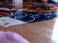
In the meantime I spent hours today cleaning and polishing my GB playfield. Ideally it needs to be restored properly but this will do for now:


I've just skimmed quickly through this thread as there have been loads of updates recently, but...
PLEASE DO SWITCH THIS MACHINE ON AGAIN UNTIL YOU GET THE MAINS TOTALLY RE-WIRED!!!
Hope that got your attention. I'd hate for a fellow pinhead to go up in smoke. That thing is a feckin' death trap! Made me feel kinda queasy just looking at those photos knowing that this was actually in someone's house, plugged in and switched on.
That secondary transformer can go. Total bollox. Ditch the white mains cable and whatever remains of the original US black cable. Get yourself a nice piece of modern 13A flex. Whilst you're in there ripping all the old **** out you can toss the US service socket outlet. No use to us anyway and it's ALWAYS LIVE, because it's on the input side of the ON/OFF switch. Get yourself a new chunky DPST ON/OFF toggle switch, the original is under-rated voltage wise.
Sorry this is such a short shouty post
In the meantime I spent hours today cleaning and polishing my GB playfield. Ideally it needs to be restored properly but this will do for now:


That PF is looking great and the colours really vivid. I was happy with my game as-is but becoming less so. What alchemy on top of the melamine foam & isopropyl alcohol was this?
I'm going to spend more time shopping the PF as am too scared of what lurks below...
I'm going to spend more time shopping the PF as am too scared of what lurks below...
As you know, cleaning was done with ME+IPA. Carefully, although I have to say the playfield was very robust and I would have had to really hammer away at it to suddenly go straight through the paint down to the wood without noticing. The IPA slightly softens the old varnish so that the ME can scrub it off slightly. That's why the dirt comes off so well. Ideally though it's the first stage in a full restoration - filling in gaps, spraying new paint, uncupping inserts, etc., and then clear coating. But I haven't got time for that just now so I'm "pausing" by applying several generous coats of Mill Wax and then topping it with Lexan until the time comes to do it properly.
Hi @astyy, just quickie as it's late but snapped a few shots of the trough switch. Mine exactly the same yours although I think the wire has been replaced/botched on yours:
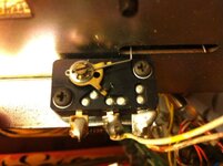
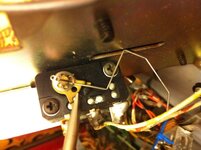
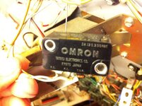
I had a rummage in my box of ex-display bits'n'bobs from my Maplin days but no micro switches as chunky as that. I don't think the voltage or current rating is of concern, just that physically it's quite a big switch.
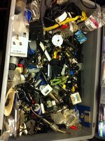


I had a rummage in my box of ex-display bits'n'bobs from my Maplin days but no micro switches as chunky as that. I don't think the voltage or current rating is of concern, just that physically it's quite a big switch.

I should have looked more closely at the number printed on the side but it looks as though OMRON still make an equivalent and that Farnell stock them:
http://uk.farnell.com/omron-electronic-components/d2mc5el/microswitch-rotary-spdt-5-1gf/dp/2213935
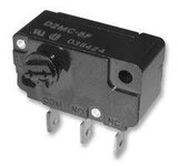
I'll check the code tomorrow. Data sheet says you can make your own actuators out of 0.6mm piano wire. I may even have some of that in my model railway bits. I use it for operating points using servo motors!
http://uk.farnell.com/omron-electronic-components/d2mc5el/microswitch-rotary-spdt-5-1gf/dp/2213935

I'll check the code tomorrow. Data sheet says you can make your own actuators out of 0.6mm piano wire. I may even have some of that in my model railway bits. I use it for operating points using servo motors!
@Nedreud you have a man down in your parts bin!
Thanks for your pictures and finding this but I'm a bit confused. According to the below schematic the switch isolating diode connects COM to NO, and on the game we wire to NO and NC. What I don't get is the game diagnostics reports the switch closed when the Goldball is closing the activator to NO but this would appear to be an open circuit based on the below.
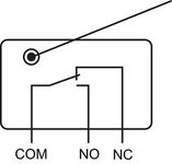
Thanks for your pictures and finding this but I'm a bit confused. According to the below schematic the switch isolating diode connects COM to NO, and on the game we wire to NO and NC. What I don't get is the game diagnostics reports the switch closed when the Goldball is closing the activator to NO but this would appear to be an open circuit based on the below.

Hi @astyy. You can just about make out in the 3rd photo where I'm holding the switch wires that the contacts are labelled left-to-right N.O. -> N.C. -> COM.
Flipping these over to reference your diagram above it would be COM NC NO. Looking at mine I think the wires are white with brown and yellow traces, so 56 and 53.
(I edited this to convert the ASCII text diagrams into an image because the white-space was collapsing so it looked rubbish):
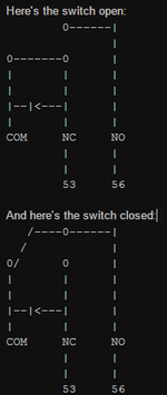
Think that's how it works. It's just convenient to mount the diode across the COM-NC contacts so that it's only brought into circuit when the switch is closed. On the new switch you'd have to swap the wire positions and bridge the diode across the outer terminals.
I think I've got those wire colours correct because the junction of 56-53 is position #30 in the matrix. Checking in the manual on page 17 the OUTHOLE GOLD BALL is #30:
56----NO----0----0---->|----COM----53
Flipping these over to reference your diagram above it would be COM NC NO. Looking at mine I think the wires are white with brown and yellow traces, so 56 and 53.
(I edited this to convert the ASCII text diagrams into an image because the white-space was collapsing so it looked rubbish):

Think that's how it works. It's just convenient to mount the diode across the COM-NC contacts so that it's only brought into circuit when the switch is closed. On the new switch you'd have to swap the wire positions and bridge the diode across the outer terminals.
I think I've got those wire colours correct because the junction of 56-53 is position #30 in the matrix. Checking in the manual on page 17 the OUTHOLE GOLD BALL is #30:
56----NO----0----0---->|----COM----53
Last edited:
I think I've got those wire colours correct because the junction of 56-53 is position #30 in the matrix.
You need my switch matrix! On that you can instantly reference the wire colours going to switch #30 which appear to be correct (phew!)
Seriously I'm glad I wasn't going bonkers about how the 'leccy work, comparing your photo with the stock photo off Farnells they appear to have switched the terminal order and it's now per the schematic so will need re-wiring back differently as you point out.
Have you had a chance to check that is the correct switch?
Last edited:
Grr... just noticed the white-space in my beautifully constructed ASCII diagram had collapsed so they look rubbish! Here's a screenshot whilst editing:
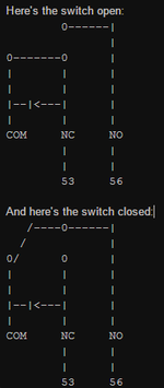
I'm pretty sure that's the right switch. It seems to be the right size physically. Need to double-check if it's Clockwise or AntiClockwise activated. Will have to be later tonight... I'm off lunch now

I'm pretty sure that's the right switch. It seems to be the right size physically. Need to double-check if it's Clockwise or AntiClockwise activated. Will have to be later tonight... I'm off lunch now
I'm pretty sure that's the right switch
Agreed, the markings on the top of mine look similar to yours, these Cherry ones look very similar;
http://uk.rs-online.com/web/p/microswitches/0339207/
Those Cherry ones look good too. Same thing with the NO and NC positions being different but that really makes no difference. Both Cherry and OMRON are quality brands.
I'm sure pretty much any microswitch you could fettle into position would work.The switch matrix is only +5V data signals. I suspect it's only a whopping great big 6A @ 250 VAC switch is because back when the first under-playfield outhole kicker was designed this is what they had to hand in the 70s and the rotating switch shaft probably lent itself well to how it operates. The design/spec probably continued into the 80s.
I'm sure pretty much any microswitch you could fettle into position would work.The switch matrix is only +5V data signals. I suspect it's only a whopping great big 6A @ 250 VAC switch is because back when the first under-playfield outhole kicker was designed this is what they had to hand in the 70s and the rotating switch shaft probably lent itself well to how it operates. The design/spec probably continued into the 80s.
The Cherry also gets an extra +1 for coming with a pref-formed bit of piano wire 
Gold Ball Outhole micro-switch sorted - for future reference the Cherry E51-60B was a great replacement for the original Omron and the original lever clipped straight on but note different order of terminals. Played a couple of games after and it was working well - I'm sure this switch going was confusing the logic when the regular ball drained.
Then fitted a nice 250VAC DPST toggle per @Nedreud recommendation. That feels far more solid.
Then removed the "alien transformer" stepping down the input voltage to the regular transformer to 210V - the GI now noticeably brighter.
Still o/s to fit a new power cord - can you get UK ones with molded plugs to suit?
I thought I was back in business but now one of my displays is playing up but I know where to start with them.
Old switch a dangling....
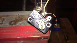
Nice new Cherry switch in situ - note diode now between outer terminals behind
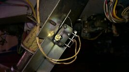
Then fitted a nice 250VAC DPST toggle per @Nedreud recommendation. That feels far more solid.
Then removed the "alien transformer" stepping down the input voltage to the regular transformer to 210V - the GI now noticeably brighter.
Still o/s to fit a new power cord - can you get UK ones with molded plugs to suit?
I thought I was back in business but now one of my displays is playing up but I know where to start with them.
Old switch a dangling....

Nice new Cherry switch in situ - note diode now between outer terminals behind

CPC do range of bare-ended mains cables with moulded 13A plugs in different lengths. Personally I'd go for the 1.5mm as although the others (0.75mm and 1.0mm) are rated to deliver sufficient current the 1.5mm will be a thicker, harder wearing cable.
2m, 3m, 5m and 6m in black or white:
http://cpc.farnell.com/pro-elec/pe01023/lead-uk-plug-bare-end-blk-1-5mm/dp/PL13286
![42409544[1].jpg 42409544[1].jpg](https://www.pinballinfo.com/community/data/attachments/13/13937-36b92c11c283347dbdb51b236d39181b.jpg?hash=NrksEcKDNH)
PS. Double
 for getting rid of that other transformer!
2m, 3m, 5m and 6m in black or white:
http://cpc.farnell.com/pro-elec/pe01023/lead-uk-plug-bare-end-blk-1-5mm/dp/PL13286
![42409544[1].jpg 42409544[1].jpg](https://www.pinballinfo.com/community/data/attachments/13/13937-36b92c11c283347dbdb51b236d39181b.jpg?hash=NrksEcKDNH)
PS. Double

 for getting rid of that other transformer!
It's been bypassed but still lurking in the depths of the machine taunting me!Doublefor getting rid of that other transformer!
The other thing on my list is to bypass the service outlet - I'll remove the wiring but probably leave the socket and bracket in place cos I think it's quirky.
Certainly thanks to @Nedreud and @Jay Walker for their input on my wiring else I wouldn't have uncovered the mains togethor twisted wiring in the backbox - as Ray on the Pinball series on Youtube says 'nothing good is ever found under electrical tape'.
Ok, I think I've got to the bottom of the intermittent problem that founded this thread that I want to record for prosperity. Basically on Bally Gold Ball the P-L-A-Y - A Lane rollover was intermittently activating Tilt - it would do it for some time then revert to normal. Today it took a turn for the worse and was behaving this way repeatedly - good, easier to troubleshoot methinks. ( Initially I thought the machine had heard about visitors at the weekend wanting to play it causing the fault but that didn't make sense.)
On switch test the A lane (switch 23) was repeatedly activating Tilt (switch 15 of x3) but no other Switches were reporting closed and each reported their own number correctly (inc. 3x Tilt, 2x Slam, 3x Coin Mech, 1x Credit button so all good on the door).
Then I found a similar report on pinside with a tip to clip the Cap on the Tilt mechs as not required for home use - initially I couldn't see any but then found one lurking behind the Plumb Bob Tilt - upon clipping this a RESULT A lane reporting it's correct assignment again and all is well until the next episode.
Thanks @Moonraker a small victory but it felt good! I saw you have a Haunted House tucked away in the corner last Saturday - will that be up and playing soon? Would love to play one of those (as well as all your other machines)
I saw you have a Haunted House tucked away in the corner last Saturday - will that be up and playing soon?
Sadly that's a very long term project rebuild...
Bet it's finished before PARAGON...Sadly that's a very long term project rebuild...
Bet it's finished before PARAGON...
You're miles ahead of me on that score...
Some might say all that glitters is not gold, whilst others may say you can't polish a turd. Whilst I'm certain this isn't the case for PARAGON I'm not 100% sure about GOLD BALL 
I read up on this...Uk is now officially 230V AC +10% to -6% So not far off tolerance anyhow
What’s the significance of ‘TwoThirtyVolts’?
In the UK, mains electricity is currently required by law to be delivered at 230 Volts, within a tolerance of +10% / –6%, that is, within the range 253 Volts to 216.2 Volts. The value of 230 Volts is said to be the ‘nominal voltage’
In an electrical system, ‘voltage’ is the equivalent of ‘pressure’ in a water system, (current being the equivalent of water flow rate).
History of the nominal voltage in the UK
In 1994, to remove a perceived barrier to trade between European countries, the European Commission (EC) decided to ‘harmonise’ the standard UK mains voltage of 240 V and the European standard of 220 V at 230 V.
However, the cost of replacing or adjusting all the electricity supply equipment across Europe to actually deliver 230 V was prohibitive, there being no technical advantage whatever in changing, other than ‘harmonisation’.
So, to avoid accusations of failure to harmonise, the European Commission simply altered the legal voltage limits - nothing actually changed!
The law in the UK currently states that the mains supply voltage must be 230 V +10% / -6%, thereby allowing the European 220 V system to stay at 220 V and the UK to stay at 240 V, yet both appear to be harmonised!
In 2010, the voltage tolerance band may be increased to +10% but again, in reality, nothing will really change!
Effective date
Nominal voltage
Permitted tolerance
Permitted voltage range
Pre-1995
240 V
+6 % / -6 %
225.6 - 254.4 V
1 January 1995
230 V
+10 % / -6 %
216.2 - 253.0 V
April 2010 (proposed)
230 V
+10 % / -10 %
207.0 - 253.0 V
So, it would appear that it more likely that 240V will pour out of your average mains socket than 230V but could be anything between 216V and 253V and that would be considered quite normal and within tolerance.In the UK, mains electricity is currently required by law to be delivered at 230 Volts, within a tolerance of +10% / –6%, that is, within the range 253 Volts to 216.2 Volts. The value of 230 Volts is said to be the ‘nominal voltage’
In an electrical system, ‘voltage’ is the equivalent of ‘pressure’ in a water system, (current being the equivalent of water flow rate).
History of the nominal voltage in the UK
In 1994, to remove a perceived barrier to trade between European countries, the European Commission (EC) decided to ‘harmonise’ the standard UK mains voltage of 240 V and the European standard of 220 V at 230 V.
However, the cost of replacing or adjusting all the electricity supply equipment across Europe to actually deliver 230 V was prohibitive, there being no technical advantage whatever in changing, other than ‘harmonisation’.
So, to avoid accusations of failure to harmonise, the European Commission simply altered the legal voltage limits - nothing actually changed!
The law in the UK currently states that the mains supply voltage must be 230 V +10% / -6%, thereby allowing the European 220 V system to stay at 220 V and the UK to stay at 240 V, yet both appear to be harmonised!
In 2010, the voltage tolerance band may be increased to +10% but again, in reality, nothing will really change!
Effective date
Nominal voltage
Permitted tolerance
Permitted voltage range
Pre-1995
240 V
+6 % / -6 %
225.6 - 254.4 V
1 January 1995
230 V
+10 % / -6 %
216.2 - 253.0 V
April 2010 (proposed)
230 V
+10 % / -10 %
207.0 - 253.0 V
Ok, I think I've got to the bottom of the intermittent problem that founded this thread that I want to record for posterity. Basically on Bally Gold Ball the P-L-A-Y - A Lane rollover was intermittently activating Tilt - it would do it for some time then revert to normal. Today it took a turn for the worse and was behaving this way repeatedly - good, easier to troubleshoot methinks. ( Initially I thought the machine had heard about visitors at the weekend wanting to play it causing the fault but that didn't make sense.)
On switch test the A lane (switch 23) was repeatedly activating Tilt (switch 15 of x3) but no other Switches were reporting closed and each reported their own number correctly (inc. 3x Tilt, 2x Slam, 3x Coin Mech, 1x Credit button so all good on the door).
Then I found a similar report on pinside with a tip to clip the Cap on the Tilt mechs as not required for home use - initially I couldn't see any but then found one lurking behind the Plumb Bob Tilt - upon clipping this a RESULT A lane reporting it's correct assignment again and all is well until the next episode.
Each of the two Stern 'Ali' machines I've owned had a problem with false pendulum tilts. In each case there was also no capacitor across one of the stand-up targets (the 1st 'T' of 'Greatest'); adding one caused the target to register of its own accord. Both of these were rectified by disconnecting the 3-pin power outlet on the white-painted wooden tilt panel inside the cabinet. I've never been entirely sure why, but suspect it was an earthing problem - the earth braid ran behind the tilt panel.
Ali is a game where it's almost routine to 'roll' the scoring, by exceeding 1 Million points. I once had the scoring stop on 999,990 with the final ball in the outhole, but the tilt didn't register when I pushed the game to avoid adding the bonus. Stern games didn't make the High Score award when they were rolled, either.
Last edited:
Good point. Poor earthing is an issue on many games of this era. There are multiple mods to the boards themselves to improve ground connections. Knowing some of the power supply hacks on @astyy's GOLD BALL it wouldn't surprise me if one or more improvements could be made to the ground wiring. I'm going to rip the earth braid out of mine and do it again. Properly. US electrical standards were a bit flaky 30+ years agosuspect it was an earthing problem
Things are playing up again. I noticed that all the GI on the backbox is out. On lamp test, half of the backbox feature lights are out too (Match, Gameover, HiScore, #2 Mill, #3 Mill). These are all common from A2 J3-11 on Phase A. (Note @Nedreud I think the manual is wrong and has #3 Million and #4 Million the wrong way round on the backbox Wiring Schematic - no surprise I'm sure you'll say!)
I've checked the basics, fuses, earth, continuity, TP's on A2.
I'm sure these two things are related and perhaps to do with the GI flasher but this is getting beyond me.
Any advice appreciated.
I've checked the basics, fuses, earth, continuity, TP's on A2.
I'm sure these two things are related and perhaps to do with the GI flasher but this is getting beyond me.
Any advice appreciated.
I took measurements directly off the transformer whilst it was out of the machine. This isn't 100% reliable/realistic as it's not under load conditions, but always good to know that your multi-tap transformer is at least kicking out roughly what you're expecting before hooking it up to everything else.
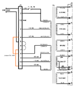
Your voltage readings look fine. Have you checked fuse F6, that's for the backbox GI? Both F6 and F7 (the fuse for the playfield and cabinet) are fed by J5-12 in the diagram below. This is where you should be getting ~6.5 VAC, across J5-12 and J5-8. J5-12 feeds F6, which goes to J4-8 and J4-9 for the backbox, and F7 which goes to J2-6 (cabinet) and J1-1 and J1-4 (playfield).
Now those GI flashers are a f***er. They're obsolete TRIACs and I think one of mine is dead because someone hardwired the playfield GI to always be on. During the time I had the game running I wasn't aware of the GI control so didn't notice if the backbox GI ever flashed. It's one thing I need to check and test thoroughly when the playfield rebuild is done. You could try switching the connectors on the TRIACs (the two big things bolted on the front corners of the transformer board in the base of the cabinet) and also try swapping over the GI FLASHER MODULES, both of which are mounted on the back of the light board in the backbox.


