What's new
Pinball info

Register a free account today to become a member! Once signed in, you'll be able to participate on this site by adding your own topics and posts, as well as connect with other members through your own private inbox!

Gold Ball - Intermittent Problems

astyy

Play Flipper Games for Fun and Recreation
5Years
Joined
Jan 19, 2015
Messages
3,120
Location
Basingstoke
Hi All, this is my first post here. I got a Gold Ball last summer that had been in outside container storage for several years, known working(ish) when went into storage. Fortunately it only had minor problems which I resolved one by one and the machine was working great and enjoying playing it (famous last words!). I also removed half of Brighton beach from the PF how the heck does that get in there.

However, now it is behaving strangely, in particular Solenoids 01 - 07 stopped working. I unplugged the sound card and they were back on. Having re-plugged the sound card back all appeared ok again but now it's reacting very slowly for example when the ball drains it takes ages to reset.
I'm thinking it's something more fundamental and I need to check the machine and implement sensible upgrades ground up, being a newbie I went for the straight switch on approach at the time.
I'd appreciate some general advice for t/shooting approach to follow - this article 'Repairing Bally Electronic Pinball Games from 1977 to 1985' appears to be a great resource for this machine.

Thank you for any advice.
 
Hi, astyy,

If the machine was stored for years, you'd be well advised to check/remove/replace the back-up battery on the lower edge of the Mpu board in the backbox. They're notorious for releasing corrosive leakage over the circuit boards, which can creep into the sockets for the i.c. 'chips', and eat away the copper traces.

'Nedreud' has a Gold Ball under renovation at the moment, with its own thread in the 'Shop Logs' section.

The repair guide (which I can't link to at present) might not take into account that Gold Ball uses a special 'combo' circuit board rather than the standard Solenoid Driver (SDU) and Lamp Driver (LDA) boards.
 
Last edited:
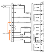
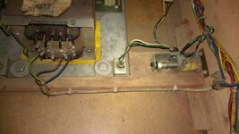
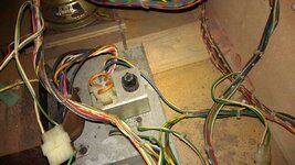
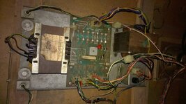
Does this look right? I appear to have an extra transformer connecting to 240 and 220V with some electrician looking lead and cable clips, I don't get this the power supply schematic (labelled GRAND SLAM in the manual) shows that J1 can be jumpered to 240VAC.

WP_20150119_18_34_45_Pro[2].jpg
 
Hello, @astyy! I see you're from Basingstoke and I've got a feeling you emailed me directly via pinballowners.com... yes, just checked.. it was you. HUGE SORRY for not replying :oops: I kept meaning to... but now that you're on here too you can pester me all day and probably get an answer quickly as I'm on here almost every day!

As @Jay Walker mentioned I have a shop log on here for my GOLD BALL (link in my signature below and Flickr photoset too).

First up, that second transformer is mostly definitely non-standard! I can't make out what it's doing? I can see what looks like mains going in but what's coming out? Is it perhaps a step-down transformer to drop 240VAC to 110VAC, installed by someone who didn't realised that connector J1 can be re-jumpered for various input voltages? Yours looks like it's correctly jumpered 4-8 and 7-11 for 240VAC.

Power Supply Schematic.png

Word of warning, the GOLD BALL manual is full of minor errors. It doesn't help that the schematics on the IPDB copy are almost illegible. Best thing I did was to get an original manual. At least I can read the schematics. I've been meaning to dig out my flat-bed scanner from the back of the storeroom and upload a new copy to IPDB. Maybe I should pull my finger out and get a copy to you ASAP! :D

It's interesting that removing the SOUND MODULE connection fixed your solenoid issues. If you look at the schematic you'll see that connector J4 on the A2 MPU module has an output on Pin 10 (A2J4-10) labelled "SOLENOID BANK/SOUND SELECT". This controls whether the data on pins A2J4-1, A2J4-2, A2J4-3 and A2J4-4 are controlling the solenoids or sounds. Note these 4 pins (data lines PB0/1/2/3) run to both the A8 SOUND MODULE (A8J1-1/2/3/4) and the A3 LAMP SOLENOID REGULATOR COMBO (A3J4-6/7/8/13) - although A3 only uses PB0, PB1 and PB2 - I'll need to go check that A3J4-13 is even connected. This is a perfect example of where the manual doesn't quite tell the whole truth! With only 3 data lines a maximum of 8 momentary solenoids can be controlled - GOLD BALL has 7. I wonder if you got some dodgy connections; either dirty contacts, dry solder joints or broken wires? As re-seating the connector partially fixed the problem I'd start looking there.

As Jay mentioned if there is battery corrosion on the A2 MPU this can cause all sorts of random problems. How does your board look?

The repair guide you've been following is my bible too. I think it's what used to be known as "Clay's Guide". I use the copy hosted here: http://techniek.flipperwinkel.nl/ballyss/rep/index1.htm

Yes, do be aware the A3 COMBO board is a different. It was only used on GOLD BALL and GRAND SLAM, and is different again from the combo board on BABY PACMAN or GRANNY AND THE GATORS. There's not much information about it on the internet. There's not even a photo on PinWiki (I've been trying to get an account to edit the pages there to add what I know). It's similar, if somewhat reduced, to the separate boards, but it doesn't need to mods as detailed in that repair guide as the design is better.

Anyway, welcome to the forums! It's a great place here and everyone is so very helpful! There are folks with a long history and knowledge of pinball, and some folks with mind-blowing knowledge in the field of electronics and repair. If there's anything I can help with your GOLD BALL just ask! PM me if you're in the area and want to to drop in for a cuppa. I'd let you have a game but as you can see in my shop log GB is in pieces at the moment!
 
Thanks all for your support. I am aware of the battery leakage scenario and embarrassed to admit I haven't tackled it yet as it appears new and shiny and I'm not sure what route to follow yet. I'll get some photos later.

In the meantime can somebody (probably @Nedreud !) confirm the TPs on the AS-2518-151. Most of them I can make out from the schematic but I'd like to double check.
I'll have to go out the workshop to grab the manual but I do recall this is another area where there's an error in the schematic: it shows two TP4 test points on either side of the +5VDC regulator circuits (bottom left corner of schematic labelled "H.V. LAMP/SOLENOID DRIVER COMB."). I think the one on the left should be TP9 and is the LOGIC GROUND, whereas the one on the right is TP4 and is the +13-16VDC unregulated. Don't take my work for it - cross-reference the schematic with the tracks on the board. And do be careful with this board as the +190VDC regulator section for the displays (the smaller of the big black heatsinks) will give you a potentially fatal shock. I also discovered that the heatsink itself is live!

One thing to check is the loop-back connection between pins 13 and 25 on connector J7. This feeds +5VDC from the regulator back into the circuits on the board! This needs to have a good connection otherwise the logic chips for the lamps and solenoids won't get a good supply. Maybe this is a potential mod for these boards? A wire bridge on the reverse permanently connecting these pins.
 
I keep forgetting the Attract sound is enabled, this scares the bejeebers out of me when I'm working inside the table with the power on testing this stuff. When will I learn, only just got used to the pinballs falling out when you lift the playfield - doh!
 
Hi @Nedreud

It's interesting that removing the SOUND MODULE connection fixed your solenoid issues. If you look at the schematic you'll see that connector J4 on the A2 MPU module has an output on Pin 10 (A2J4-10) labelled "SOLENOID BANK/SOUND SELECT". This controls whether the data on pins A2J4-1, A2J4-2, A2J4-3 and A2J4-4 are controlling the solenoids or sounds. Note these 4 pins (data lines PB0/1/2/3) run to both the A8 SOUND MODULE (A8J1-1/2/3/4) and the A3 LAMP SOLENOID REGULATOR COMBO (A3J4-6/7/8/13) - although A3 only uses PB0, PB1 and PB2 - I'll need to go check that A3J4-13 is even connected. This is a perfect example of where the manual doesn't quite tell the whole truth! With only 3 data lines a maximum of 8 momentary solenoids can be controlled - GOLD BALL has 7. I wonder if you got some dodgy connections; either dirty contacts, dry solder joints or broken wires? As re-seating the connector partially fixed the problem I'd start looking there.

It was Solenoids 01 to 07 not working which I assume are the momentary solenoids. The volume always faded over time and the pot control on A8 and coin door are scratchy, prior to the Solenoids going I was trying to synch the volume controls to max sound (it was pretty loud!) could this have impacted it. The machine is still reacting slow to events, the ball draining in particular.
 
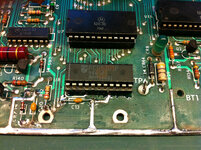
Have made some progress on this, Gold ball - Outhole switch is currently under suspicion as this game behaves odd if it thinks the Gold ball isn't seated and that is the symptom. I still need to investigate the extra transformer further but in the meantime here is a pic of the battery setup on the MPU. I'm interested in comments on this, is the damage bottom right likely caused by previous corrosion & repair as the battery appears modern. Thanks all.

WP_20150122_18_25_55_Pro[1].jpg
 
Hi,

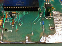
The original battery would've been a 'stick' type, about the size of an ordinary 'AA' cell, with the +ve tag soldered into the point below U8, pin 11. The similar point further left allowed the pcb to use a longer battery if required. The missing green foil/lettering probably was caused by leakage creeping under it. Is the slot-head screw securing the board in place? I know Bally were cutting costs at the time, but I think the boards in the backbox should mount onto metal rails, with plastic stand-offs and two grounding screws. It looks too close to the metallised backing for my liking.
 
Wow! That MPU looks in great condition!

Someone has very kindly removed the old NiCad rechargeable battery and replaced it with a "Supercapacitor". This is a capacitor that can hold it's charge for a long time, usually several months depending on the drain current, so it behaves much like a rechargeable battery. I got one to put on PARAGON. They're a much better replacement for a battery or coin cell if you don't want to replace U8 (5101) with a non-volatile RAM adapater (the power from the battery keeps the data in U8 after power off, but modern NVRAM memory doesn't need power to remember its data).

It look as though there may have been a little acid leakage from the original battery as the green screening has been rubbed off the bottom edge of the board, but this is because someone has cleaned it up and neutralised it. It looks good! Doesn't look as though any of the original components in the RESET CIRCUIT (the area around the big R11 resistor) have been replaced, so the acid damage must have been superficial at worst.

Also, the original 6820 PIA (Peripheral Interface Adapter) chip at U11 has been replaced with the later MC6821P (functionally the same, just some improvements in electrical characteristics). It all looks a hell of lot prettier than mine does!

farm4.staticflickr.com_3927_15524572851_37572401f2_c.jpg

farm6.staticflickr.com_5601_15341078218_d5b9eec8ae_c.jpg

That gold ball switch got me too. Usually the game just has to know there's a ball in the main trough, but GB wants to know there's one in the gold ball trough too. Not surprising really, but it had me scratching my head for 5 minutes!
 
Hi,

The original battery would've been a 'stick' type, about the size of an ordinary 'AA' cell, with the +ve tag soldered into the point below U8, pin 11. The similar point further left allowed the pcb to use a longer battery if required. The missing green foil/lettering probably was caused by leakage creeping under it. Is the slot-head screw securing the board in place? I know Bally were cutting costs at the time, but I think the boards in the backbox should mount onto metal rails, with plastic stand-offs and two grounding screws. It looks too close to the metallised backing for my liking.
Looks as though it's on a plastic mounting (bottom right). I think the "slot-head screw" you're seeing could be test point 5 (TP5)? The label is missing (see my photos in above post).
 
Thanks both. I rtfm when i first got the machine and prominent in the inner front cover is the IMPORTANT procedure to seat the Gold Ball which kind of jumped out and stuck with me.

Coincidentally after watching the Todd Tuckey Spectrum video earlier I then drifted into another of his on replacing the MPU battery and that's the first time I saw the old type that used to be fitted - had I encountered one of those I'd likely have clipped it straight off and thrown it as far as I could.

I'm now thinking that this machine had some good work (as well as bad) done on it in an earlier life. The previous owner is my mate and he had it inside for a time and then in storage for a few years and to my knowledge did little to it.
 
From http://techniek.flipperwinkel.nl/ballyss/rep/index3.htm#35roms:

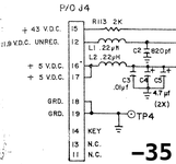
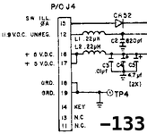
remember the -133 is really a -35 board with R113 changed to a diode CR52

That site says that the AS-2518-133 is from BABY PAC-MAN. The question is why is R113 replaced with CR52? It's to do with what's being fed into it. Looking at the schematics for a -35 vs a -133 the only difference is the first component from Pin 15 on connector J4. Traditionally on a -35 this is where the +43VDC from the solenoid power comes in that ultimately feeds the ZERO CROSSING DETECTOR circuit. This is why on almost all Bally's of this era if the F4 fuse has blown on the A2 power supply the game won't boot up because the ZCD circuit never starts (and hence no 7th flash on the MPU LED).

But, to the best of my knowledge, GOLD BALL, GRAND SLAM and GRANNY AND THE GATORS, as well as BABY PAC-MAN, were all fitted with -133 MPUs. In these systems Pin 15 is now fed with power from the ΦA channel of the SWITCHED ILLUMINATION, which is around 10VAC. The voltage is already lower, hence no need for the resistor, but as it's AC it gets a simple half-wave rectification by CR52.

If you look at the schematic you'll also notice that the voltage 21.5VDC on TP3 has been crossed out. Nothing helpful like amending the diagram with the correct test value!

AS-2518-35.png AS-2518-233.png

Sorry, that was a long walk around the houses. I only found out about all of this because my GB came with a dead -35 that had been modified but after I fixed it once it mysteriously died again, so I fixed another dead -35 I had. Took me ages to work out why I was faking the 7th flash on the test bench but not in the machine!

But to answer your actual question, the board number AS-2518-133 is correct for GOLD BALL and IPDB is wrong. I'll let them know ;)
 
Last edited:
Investigated the unusual double transformer setup today.

Here is its feed spliced into the main power feed to the normal transformer. Blue in, Brown return.

WP_20150124_14_19_49_Pro[1].jpg

Heres the connection to the transformer Blue to 240V, Brown to 220V - verified on DMM (in between Attract Sounds!)

WP_20150124_14_19_14_Pro[1].jpg

The voltage selection jumper wires - set to 240V (I think)

WP_20150124_14_21_59_Pro[1].jpg

Finally readings on TPs

TP1 215 VDC
TP2 9.5 VAC
TP3 9 VAC
TP4 38 VDC
TP5 14 VDC

So I'm not sure if I should remove this Transformer from the feed as we're supplying 220 VAC to a 240 VAC setup for no apparent reason.
 
Further progress. Been testing the switch on the Gold Ball outhole. Switch diode de-soldered and tested good but switch not conducting across Tabs when closed. Jumpered the switch and reports Closed (#30) now in diagnostics which wasn't previously so this is promising. As it need replacing anywayI tried to prise open the switch to investigate and have broken it can somebody please point me in the direction for a new one, have done a bit of Googling but it's not obvious to me which is a direct replacement. Cheers.

What it looks like in situ (but broken now)

WP_20150124_17_39_21_Pro[1].jpg

One side missing the extra two tabs

WP_20150124_17_43_24_Pro__highres[1].jpg

t'other

WP_20150124_17_43_57_Pro__highres[1].jpg
 
Hi astyy,
is the white 3-core flex in posts #3 and #20 opposite ends of the same cable? and that actually the mains comes in on another flex, possibly the black one by the speaker in post #3?

Anyway, what it looks like to me is that somebody has re-purposed that second transformer as a choke (series inductor) possibly to combat rf interference.

What i think your wiring should be is ...
Mains in L(BRN) N(BLU) E(GRN/YEL) connecting to an rf filter and coming out as L(BRN) N(BLU) E(GRN/YEL).
The filter output wires within a couple of inches change to L(WHT) N(BLK) E(CHASSIS)
The L(WHT) and N(BLK) go to an on/off switch (underneath the cabinet by the coin door) and also to the service outlet inside the cabinet.
The on/off switch output wires change to L(YEL) and N(BLU) and head over to the 'proper' transformer.

What i think your wiring actually is ...
mains in??
rf filter missing??
The L(WHT) and N(BLK) go to an on/off switch (underneath the cabinet by the coin door) and also to the service outlet inside the cabinet.
The on/off switch output wires change to L(YEL) and N(BLU) and head over to the 'proper' transformer.
The on/off switch N(BLU) is cut and connected to the 'choke' via the 3-core blu and reconnects the cut BLU via the 3-core brn. i.e. a series connection

what is of concern is the connection of the 3-core grn/yel to the on/off switch L(YEL)
This could be a shock hazard,
I can't tell exactly because i can't see the 3-core grn/yel connection to the 'choke' (more pics!)

I'm not going all health and safety but i'd hate something to happen and not have said anything!

course, if the wiring's nothing like above then i'll shut my face and keep my nose out :)
Rob
 
Send an email to The Legend @pinballmania explaining what you're after and I'm sure he'll help you out. Contact him through his website:

http://www.pinballmania.co.uk/

Thanks Ron, I have got most of what I've needed from Andy so far and this part on his site looks promising and right bolt holes but the switch lever is different;

Outhole and Trough Switch with Loop.
SW-5647-12133-12
SW-180-5011

Hopefully @Nedreud will give me a view as to what this piece is his like on his machine so I can get it ordered.
 
Thanks Ron, I have got most of what I've needed from Andy so far and this part on his site looks promising and right bolt holes but the switch lever is different;

Can the switch arm be removed from your existing switch and attached to a new one? You can do that with the more modern switches but this one looks a bit more vintage :D
 
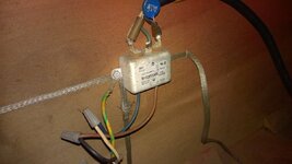
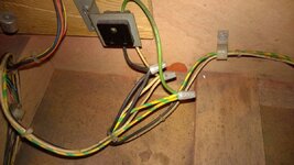
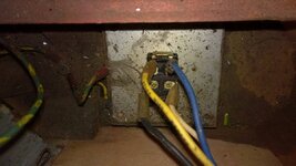
Rob @backbox, thank you for the encouragement to delve further and take more photos - I have indeed found a 'nasty'

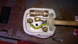
1. here is the cream lead wired to the plug - glad to see an Earth.

WP_20150125_09_58_57_Pro__highres.jpg

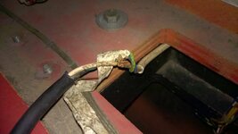
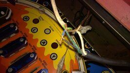
2. As you pointed out the mains cable inside the unit is black - how could this be? Then I found this lurking out of sight under the backbox.

WP_20150125_10_13_56_Pro.jpg

WP_20150125_10_56_06_Pro.jpg

3. Moving on this looks more tidy - just out of shot to the right the earth braid is severed not sure where this was heading - the speaker?

WP_20150125_10_59_09_Pro.jpg

4. Service outlet

WP_20150125_11_00_10_Pro.jpg

5. back of on/off switch

WP_20150125_11_00_43_Pro.jpg

6. diversion of blue/yellow to first transformer (note nothing connected to other side of transformer). Brown wire returning @ 220VAC to continue on as the regular blue wire.

WP_20150125_11_01_11_Pro.jpg

7. Then onto normal transformer @ 220 VAC

WP_20150125_11_01_22_Pro.jpg

8. Overview of layout

WP_20150125_11_01_40_Pro.jpg

So a few more bits on my to-do list before I ever switch it on again!

1. Sort bodged connection - new mains cable/plug right up to the filter? What spec' should the cable be? (I think @Nedreud has some good stuff in his Shop thread in this area.)

2. Is the loose Earth braid to the right of filter ok? Where should that be going?

3. Still not sure if I should remove the first transformer or jumper the connector to the second for 220 VAC
 
Can the switch arm be removed from your existing switch and attached to a new one?

The wire hook comes off as it's held in the slot with the grip washer. Not sure it comes any further apart you can see the results of my research on this.
 
Is the loose Earth braid to the right of filter ok? Where should that be going?

Have you got earth braid going up into the head? It's normally screwed to the head earth braid in the middle at the bottom. If you don't have this and that loose earth braid is long enough to go up there then I think it's probably for that. You can tell by looking at the end of the loose braid to see if it's got a hole in it where the screw would go through.

Do not turn the game on without this earth braid connected in the head!
 
hey astyy,
much clearer now with those pics.
That alien transformer is not acting as a choke as i first thought but is actually connected as an 'auto-transformer' dropping the 240V input to 220V out and dropping all the secondary voltages to boot!
This is not the same as rejigging your links at the voltage selector connector. If you connected 240 across the 220 input then the output would go up!

The transformer may have been used in an area of the UK that actually had a 250V supply and so needed knocking down a bit.

Anyway, the test point voltages you measured in post #20 look a bit low, so I would take the alien and the white 3-core out and link the 2 BLUes together at the choccy block.

good find on the mains wiring nasties by the way ... new flex straight to the emi/rf filter, job done!

good luck
Rob
 
Last edited by a moderator:
quick one while i'm at it.
measure your mains voltage, some of the UK has gone to 230.
If so, it might be worth rejigging your voltage selector connector. It'll give a bit more oomph to the solenoids.

Rob
 
Back
Top Bottom