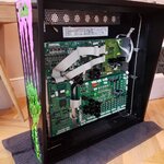
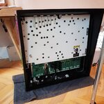
These ones are off but flash on when the pops are hit... looks great!
Pinball info
You are using an out of date browser. It may not display this or other websites correctly.
You should upgrade or use an alternative browser.
You should upgrade or use an alternative browser.
Complete Creature from the Dank Saloon **Finished** .. Full Pics!!
- Thread starter stumblor
- Start date
These ones are off but flash on when the pops are hit... looks great!
Thanks mate, reading through the guide now. I'll give it a crack
Looking insane.
Good work soldier [emoji111]
Sent from my D5833 using Tapatalk
Good work soldier [emoji111]
Sent from my D5833 using Tapatalk
Been enjoying this thread a lot. I'm so ocd but also lazy so i can't imagine being able to do such a thing!
It's rewarding even just to look at the pictures, i can't imagine what it feels like to you.
Looking at the extent of damage to machines and the lengths people go to to restore them made me curious.
It made me think of Triggers broom in Only Fools & Horses. [emoji16]
It's an original <insert pin name> except this and this and this etc.
If you can get parts made new, at what point is a pin not original?
As a noob I'm guessing you can't just replicate the board or that's the hardest bit?
Sent from my SM-G973F using Tapatalk
It's an original <insert pin name> except this and this and this etc.
If you can get parts made new, at what point is a pin not original?
Thanks David. I suppose I would only consider it original if you had used or tried to use as close to stock parts as possible. But with the wealth of options available, it's more fun to go a bit wild. I'm definitely in the 'pimp them out' camp.
Thanks David. I suppose I would only consider it original if you had used or tried to use as close to stock parts as possible. But with the wealth of options available, it's more fun to go a bit wild. I'm definitely in the 'pimp them out' camp.
Pimping out is good! I was just thinking there must be pinball purists who even if you kept it stock, would they still consider it an original? Say if the cabinet was totally remade from scratch, a new playfield, etc? Just my curious brain
Things get broken and wear out due to being hit by a heavy metal ball. The most important thing is using quality/licenced parts and ensuring the workmanship is to a high standard.
So I've got the majority of my switches soldered in now. Stupid question, what's the best way to test the switch matrix on the bench?
Ideally I'd like to test it at the connector end, to make sure all the wiring is routed correctly.
Ideally I'd like to test it at the connector end, to make sure all the wiring is routed correctly.
Looks like a proper job to me well done
D
Deleted member 2463
Looking good!
can you plug it into the backbox and use the DMD test matrix?
can you plug it into the backbox and use the DMD test matrix?
Looking good!
can you plug it into the backbox and use the DMD test matrix?
Thanks Neil - yeah this would be the best way, but at the moment it's not really and option due to being completely broken down. In my head I thought you could just run a continuity meter from one end to the other (ie column pin to row pin) but this doesn't seem to work - I guess because without all the other pins connected it creates a short?
I can test each switch individually, but ideally wanted to check the wiring as well.
To just check the wiring, I'd follow each individual colour through the harness for continuity, for each Column and Row (16 wires in all, for the normal switches). And check that each switch was the correct 'intersection' between Column and Row. For Flipper EoS switches, ring out their shared ground wire and individual 'F#' lines.
To just check the wiring, I'd follow each individual colour through the harness for continuity, for each Column and Row (16 wires in all, for the normal switches). And check that each switch was the correct 'intersection' between Column and Row. For Flipper EoS switches, ring out their shared ground wire and individual 'F#' lines.
Thanks Jay, that totally makes sense with regards to the switch harness, i'll do that.
Would you mind going into a bit more detail with what you're describing with the EOS switches - specifically what you mean by 'ring out' and 'F#' ?
The End of Stroke switches on a Williams game with 'Fliptronic (II)' solid-state controls, i.e. Addams onwards, are dedicated 'F' switches rather than spots in the ordinary matrix (as with 'Lane Change' on the older games). These switches pull their lines down to ground when closed. I don't think this game called in the spare EoS switches for anything, so there should be a common ground wire appearing at each flipper, and an individual wire for each, showing as 'F' numbers in switch tests.
'ringing out' or 'buzzing out' are sparkie terms for using an audible continuity test.
'ringing out' or 'buzzing out' are sparkie terms for using an audible continuity test.
Last edited:
It was a dark and stormy night. Winds whipped through the trees and blew neighbourly rubbish into front gardens. The idiot cursed as he picked up the 50th hobnob wrapper of the day and threw it into the bin with disgust. Raising his fists to the heavens he yelled out in pain. "Damn you Dennis! You can take my half term, but you can never take.. MY FREEDOM!"
Storm Dennis. Seriously, could they have chosen a less intimidating name? If I was a meteorologist and I was given naming rights on the next storm, and given that you have to go in alphabetical order, these are what I would have tabled:
Storm Deathdealer
Storm Dalek
Storm Darth
Storm Deceptacon
Storm Dexys Midnight Runners
Anyway you didn't come here to talk storms did ya? I hope not!
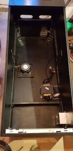
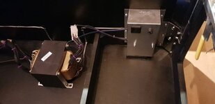
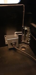
Progress has been a little bit slow over the last month, but the cab is finally finished (sans decals) so I'm working on the inside fit out. Ground wire run, power input, filter, sub, and transformer.



Last edited:
Wow oh wow. Just came across this thread. Love the hard work, dedication and love to bring this machine back up to gold standards. You are an inspiration to all of us who are tempted to do something similar but never had the balls to. Continue the shop log. It looks like a beauty already.
Absolutely stunning mate 
Absolutely loving the braided cable sleeving. Wiring on this game is gonna look so bang tidy!
Full disclosure, I got the idea from an insane Funhouse shop out on pinside! That fella only did the transformer, but I've gone and done pretty much every visible cabinet loom. Took a while but looks flash.
TonySchwager
Registered
Looks absolutely Gilliant. Fabulous work
Ok so I've moved on to the brown trousers part of the build, so buckle up and strap on the adult nappy.
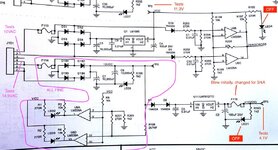
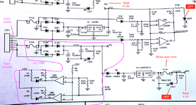
Rottendog Power Driver. Plugged all the secondary cables in after testing all the VAC numbers on the connectors. Everything looked okay so I held my breath, and turned it on. F115 went red straight away and blew. Checked the fuse and it was 1/2A instead of 3/4A, so changed over for a 750mA fuse. Turned on again and blew again.
Two LEDs not lighting, LED4 (+5V) and LED1 (+12VD).
Purple's below all look okay to me, the reds are the problems.
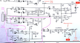
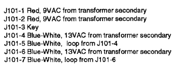
Any ideas?
Full bonerhead disclosure - I didn't have the ground strap connected when I turned it on for the first time.
Rottendog Power Driver. Plugged all the secondary cables in after testing all the VAC numbers on the connectors. Everything looked okay so I held my breath, and turned it on. F115 went red straight away and blew. Checked the fuse and it was 1/2A instead of 3/4A, so changed over for a 750mA fuse. Turned on again and blew again.
Two LEDs not lighting, LED4 (+5V) and LED1 (+12VD).
Purple's below all look okay to me, the reds are the problems.


Any ideas?
Full bonerhead disclosure - I didn't have the ground strap connected when I turned it on for the first time.
Attachments
Last edited:


