What's new
Pinball info

Register a free account today to become a member! Once signed in, you'll be able to participate on this site by adding your own topics and posts, as well as connect with other members through your own private inbox!

Bride of Pinbot helmet lights not working.

GrizzlyNate

Registered
Joined
Dec 15, 2024
Messages
28
Location
Texas
Finishing up the Bride and was so grateful on the responses I got for the motor figured I would ask her again to learn. I have the BOP and the member lights are not coming on. I habe tested the pins from J122 to the lamp board and that all shows 13.1v. Then I check the pins and all but one had 13.4v. Then trace to the helmet connections. So the connections are car-ring (to the solder where it connects) to the pins 12V as well. From the pins to the lamp sockets it drop off great ly .45 or .6 at the actual socket location. Does anyone had a wire schematiccs for this. It would be very helpful
 
Not done a a bride for a bit the 12v you are getting sounds correct but that’s only the controller part of the board you need to have the gi ac voltage as well which is more likely your problem could be something as simple as a bad fuse on the gi circuit fuses bottom left of driver board or look for burned connections on j115 j120 and j121
 
These lights are driven by the chase light board, schematics are in the manual on page 3.6.
Lamp power is provided by GI string 2 which is 6.3V AC <- IMPORTANT, measuring for DC won't show you a lot. You should have 6.3V AC on the lamps all the time, the chase light board switches to ground. You can test this by grounding the pins on J2 and 3 on the chase board - please look at schematics to see which lamp corresponds to which pin. Chase light board gets 12V on pin 5 of J1, there is a voltage regulator making 5V out of that for the logic, check for that on pin 14 of U2 e.g. Come back once you have checked the above, can be as easy as a blown fuse for GI 2.
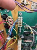
Ok. I have done checking and a little lost so will give the info I have and course correct me where I might have gone wrong. The first thing I am lost on is trying to find the ground on the chase light board. But here is what I have so far. Based on the schematics pin 4 shows a ground out if I am reading correctly. Still learning to read them based on what you are sharing. Here is a picture of the wiring into the chase board. A little confused on why there is a jumper to the key 3 pin? Just trying to make sure wires are correct as when I test I am getting 12v on all 5 pins. I am also getting 12v on pin 14 on u2. Have not ground the pins on j2 or j3 as having trouble locating the ground location on the chase board. Let me know if I am far off in left field and course correct. All fuses on the mpu are good and no issues on things coming from the pins. With the voltage making the board is it in the board for converting or am I totally missing the A/C understanding. Thanks again for all of your help.
 
I truely and new. Just switched the meter to A/C. Now just trying to figure out what to put the black line from the meter on to check the current. Sorry again for being so new at this.
 
No issue, backbox ground is fine for all of this, ie the ground braid or the metal plate behind the boards. Tuck your black cable underneath and start measuring away. With meter on AC measure voltage on the lamps in the helmet, should be 6.3 volts. You can ground them at the pins of the chase light board for testing. Don’t do that on the lamps as you have to make sure to ground the pin going to the chase board, not the one going to power or your fuse will blow!
12V on pin 14 would be very bad as that would have burned up the logic chips. Hope that was a measurement error.
Ok here is with the black cable in the braid in the back box with the meter set to A/C. This is in test mode with the helmet lights turned on in testing. It’s a video showing what the meter is reading. I start with pin 5 on J1 and the do pin 14 on u1 and or u2 based on schematics. Then I test a pin on j2. I know I am missing something but this is the best way me to share without being lost.

On the 13V was measured on the DC side with just the machine on and testing pin 5 on j1 and pin 14 on U2.
 
The videos. Had to redo them. First one is pin 5 j1, second is pin 14 u2, and third is pin 3 on j2.
 

Attachments

That doesn’t look right. First, you shouldn’t have any AC on U2, that should be 5V DC. Second, did you measure on J3 with the connector on or off? You need to either measure with connector on or inside the connector with it off. Should show a stable 6v AC. The readings all look bogus, nothing stable there. Take a short cable, connect one end to ground, poke the other end into J2/3. Lamps should light up. Measure DC at U2 pin 14 to ground. Report back.
 
That doesn’t look right. First, you shouldn’t have any AC on U2, that should be 5V DC. Second, did you measure on J3 with the connector on or off? You need to either measure with connector on or inside the connector with it off. Should show a stable 6v AC. The readings all look bogus, nothing stable there. Take a short cable, connect one end to ground, poke the other end into J2/3. Lamps should light up. Measure DC at U2 pin 14 to ground. Report back.
Ok so I took the ground cable and ran it down both J2/3 and the lamps lit up as I inserted into the back of the pins that were connected.

On DC V. Pin 5 on J1 has 13.89V at that pin. I then checked the next chip which I thinks U1 it had 13.89V at pin 14. Proceeding to chips at U2 and U3 as they both look like they are the same per the schematics one for each side of the lamps. They both also had 14V at pin 14.

Let me know if I have missed something.
 
Hmmm, seems my last reply didn't go through. This is bad actually, seems like your voltage regulator U6 LM7805 has failed short and is putting 14V into the logic chips. They won't have survived that. I assume no lights are working at all? This will be U2-5, two 74LS244 and two 74LS164. Can you solder? If not, where are you (hopefully not Texas...)?
 
Hmmm, seems my last reply didn't go through. This is bad actually, seems like your voltage regulator U6 LM7805 has failed short and is putting 14V into the logic chips. They won't have survived that. I assume no lights are working at all? This will be U2-5, two 74LS244 and two 74LS164. Can you solder? If not, where are you (hopefully not Texas...)?
Oh I can and will be able to fix that just have to order the chip sets and voltage regulator. I’ll have to shoot a picture but looks like there are 5 chip sets on the board and u6. I take it just changing out u6 first and testing is not the best. I need to change out everything that would be fried? Just let me know what all needs to be changed as already had to fix a mpu board on black knight 2000 but got to chase down more issues. I also have an eprom writer so I guess I could un solder them all and check them to see if bad. I have the tools and skill on that end just not the knowledge on understanding the schematics.
 

Attachments

  • IMG_5077.webp
    IMG_5077.webp
    30.3 KB · Views: 4
  • IMG_5061.webp
    IMG_5061.webp
    192.3 KB · Views: 4
LM7805 is short circuit proof (also, this isn't your problem, the downstream chips aren't shorted through or your fuse would blow). Just make sure there isn't any other short to +12V anywhere. Would change U6 first, and make sure you have +5V Vcc at the chips afterwards. Then test just for fun followed by changing the chips socketing them in the process.
 
LM7805 is short circuit proof (also, this isn't your problem, the downstream chips aren't shorted through or your fuse would blow). Just make sure there isn't any other short to +12V anywhere. Would change U6 first, and make sure you have +5V Vcc at the chips afterwards. Then test just for fun followed by changing the chips socketing them in the process.
So as I am trying to make sure I get the right part and zoomed in as much as I can for U6 I can not for the life of me see the part number for this regulator? When it comes to things like this is it easy just to know the part or is there another way to get the part number?
 
I figured it out as I could see the part number on the part. My question would still apply though for anything that might now have the part number. I appreciate all the help but I also want to learn as I know I want to be able to not only do these things but down the road share the knowledge as you have with me.
 
Thanks. Got parts ordered and I’ll start with the power regulate and report back as that part and then go from there. Thanks again.
 
LM7805 is short circuit proof (also, this isn't your problem, the downstream chips aren't shorted through or your fuse would blow). Just make sure there isn't any other short to +12V anywhere. Would change U6 first, and make sure you have +5V Vcc at the chips afterwards. Then test just for fun followed by changing the chips socketing them in the process.
So in testing the voltage regulator that was on the board did test good but I changed it out with a new one. Still have 13DC V on all the chips at pin 14. Now totally stumped.
 
Strange. Do you have 13V at the output of the voltage regulator? How did you test the old one? Your DMM is OK?
 
tested the old one using a multimeter following something I found. Just used the continuity on the multimeter. The meter is ok as when I test other things like the mpu and touch the points it matches the 12v, 5v and 20v points on that board. I have 13.3v on ever pin of J1. I also have 13.3V on all three legs of the voltage regulator. I have no likes on the helment working but when I do a natural ground to the pins on J2 and J3 all the different lights individually light up. All this is with the machine on.

Now when I go into the test menu and have it cycle the helmet lights this does change some readings. Pin 5 on J1 drops to .6v total, u6 has 13v on the outer leg and 10v on the middle and other leg. Then on pin14 of u2 and u3 drop to 10v. Not sure any of it matters but just sharing as I am trying to share all the info I can.
 
Strange. Do you have 13V at the output of the voltage regulator? How did you test the old one? Your DMM is OK?
tested the old one using a multimeter following something I found. Just used the continuity on the multimeter. The meter is ok as when I test other things like the mpu and touch the points it matches the 12v, 5v and 20v points on that board. I have 13.3v on ever pin of J1. I also have 13.3V on all three legs of the voltage regulator. I have no lights on the helmet working but when I do a natural ground to the pins on J2 and J3 all the different lights individually light up. All this is with the machine on but not testing. Just powered on.

Now when I go into the test menu and have it cycle the helmet lights this does change some readings. Pin 5 on J1 drops to .6v total, u6 has 13v on the outer leg and 10v on the middle and other leg. Then on pin14 of u2 and u3 drop to 10v. Not sure any of it matters but just sharing as I am trying to share all the info I can.
 
Ok, please check R7/8/9, they should be 10kOhm. You may need to lift them to check. Pin 1 and 2 of J1 are the control lines, they need to be checked with a scope. What do you have on pin 1 and 2 of U1?
 
Last edited:
Just re-reading. Pin 5 of J1 drops to .3 V? That is wrong, this is the voltage supply. Pull of J1 and measure voltage on pin 5 when disconnected from the board, do you have power there?
 
And check F116.
Also, just noticed that the schematics in the manual have the pinout of J1 reversed. :-(
So power is on Pin 1, the grey/yellow cable. Does that have 13V at all times? Checking the resistors as per above still needed as these are connecting 12V from LM339 to the 5V bus.
 
Back
Top Bottom