Hi, Purchase,
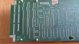
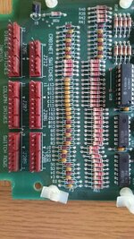
The four coin inputs and the four test buttons are all 'D' (Dedicated) switches, and register by connecting to Ground/Earth, so I suppose you could determine if the Cpu board or the machines' wiring is faulty by disconnecting J205 (bottom left of pcb, 12-pin connector) and using a jumper wire to ground the relevant pins of the cpu board;
- Enter, Switch D8, is pin 8
- Volume Up/+, Switch D7, is pin 7
- Volume Down/-, Switch D6, is pin 6
- Escape/Service Credit, Switch D5, is pin 5
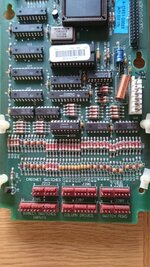
If the button functions work when using this method, the wiring's broken somewhere, but if they don't then the Cpu is faulty. The switches affected access the data lines via diodes D11 & 12, 'comparator' circuits in U16, and U15.
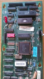
Incidentally, I notice in your pictures that the erasure window in the program E-PROM, U6, isn't covered up. There's a
faint chance the program could be affected by exposure to light; the erasure devices use prolonged UV light, but it's best to cover the window.
")
![DSC_0052[1].JPG](/community/data/attachments/13/13307-6c9d19bae6db3f14c1ec3fd38cfd4fdf.jpg?hash=bJ0ZuubbPx)
