What's new
Pinball info

Register a free account today to become a member! Once signed in, you'll be able to participate on this site by adding your own topics and posts, as well as connect with other members through your own private inbox!

Bally Sound ROMs

Nedreud

Registered
10 Years
Joined
Feb 12, 2013
Messages
3,092
Location
Aldershot, UK
Hello Pinheads!

Having a problem with the AS-2518-51 sound board in my GOLD BALL. It's gone from making only 1 sound to no sounds. I've had it on the test bench with computer PSU supply good +5VDC and +12VDC, and wired up a separate speaker. I can hear the amplifier humming and at one point I slipped with the oscilloscope probe and triggered one sound once. I've replaced the MC6821P PIA as I have plenty of spares. Maybe the MC6808P CPU is now toast? I'm going to get some MC6802 CPUs with the built-in memory so I can ditch the external 6810 memory in U10. If the technically inclined among us (@lukewells? @myPinballs?) has any advice or experience I'd be most grateful :D

But...!!!

Looking at the ROM chip the masked number is E-781-05, which as best I can tell from Googling around is from FUTURE SPA (781) and not GOLD BALL (896)!

E781-2 : Future Spa U4 Sound
E781-5 : Future Spa U4 Sound (opt)


If anyone has a really good list of Bally sound ROM numbers do please share!
 
Great sound board, lovely design :)

Ok, first things first, what is your reset section doing? On those boards the reset section is created from U6, CR2, C12 & R20. I've had issues on the board with U6 before being flakey. If you don't get a solid reset signal in a timely manor then the board says 'no thanks'

Next ditch the masked rom and get a proper eprom programmed, most likely a 2716 (contact me directly if you want help with that). Think from memory no jumpers need changing, but need to check that

Changing the processor for a 6802 is also a good idea. Jumper change will be needed here
 
Ok, update no the sound rom front. Checking my archive i have a 32K sound rom U4 for goldball, not a 16K one like on future spa. Also, if using a 2732 ic then you'll need to make a small change on the board for A11 to route to pin21. I believe the board could only be jumpered for 2716 or 2532. 2532's are long gone !
 
Last edited:
Thanks, Jim! I knew tagging @myPinballs into my post was a good idea ;)

I did a bit more testing on the bench today. First up there are a bunch of errors in the A8 schematic for the J1 connector. So, I traced the wiring, cross referenced with some other manuals and with the main loom wiring schematic. From that I was able to put together a 15-pin Molex connector to supply +5VDC and +12VDC from my bench PSU instead of jumpering to the TP test points. The main thing being that in the GOLD BALL loom pins 6, 12, 13, 14 and 15 all grounded.

Next up I pulled the 6821 PIA (U2) and 6810 SRAM (U10) and tested in a working MPU - both are ok. At least that eliminates 2 of 5 big chips.

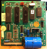
On the 'scope I can see the clock signal generated by the 6808 going everywhere it should. I can only assume that as the 6808 is still generating a clock that the rest of it is still working. But probing elsewhere doesn't seem to shed much light on what's going on. On the MPU almost all the pins on the big chips have fluctuating digital signals as data is bounced back and forth, but it all seems very quiet on this board:

GoldBall_AS-2518-51.png

As you can see it's a bit of hacky mess. I'm not happy with the massive 4,700uF 35V cap for C15 although it checks out ok. You can see C8 has been replaced and the volume trimmer is just awful. Going to see if I can squeeze in something a bit more finger friendly like this:

9608176-40[1].jpg

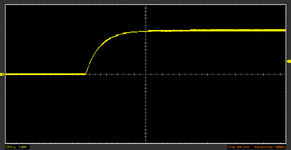
U9 also seems to be running pretty hot and I don't like the look of C7 much. The ceramic is cracking off C12 in the reset circuit but as best I can tell it, and U6, are working ok. 5V is coming out of U6 on pin 4. Here's a trace of the charge on C12 which takes just under 2 seconds. Is this a sufficient delay on the reset?

C12.png

On the ROM front the manual says U4 can be either a 2716 (Jumper C) or 2532 (Jumper D). I'm going to need the correct ROM as it'd be so wrong to play GOLD BALL with a FUTURE SPA sound set! If you are able to sort me out an EEPROM with the correct image I'd be most grateful. Let me know how much?

As for the GI AY-3-8910 it was working as when I first powered up GOLD BALL I got a few chimes and some swooshes up and down. I can pull this chip and test it with my Arduino: http://playground.arduino.cc/Main/AY38910

I also made my first order on Alibaba... 10 x AY-3-8910s for just under £9. Might take a month to get here from China, but less than a quid each seemed like a bargain to me! Also, ordered 10 x MC6802s from China via eBay for a tenner!
 
So after a bit more "prodding" the A8 SOUND MODULE has complete given up. Not a squeak.

I've tested two of the chips, the 6821 PIA and 6810 SRAM, as they are also used in the A4 MPU MODULE. Of the big chips that leaves the AY-3-8910 PSG (Programmable Sound Generator), the MC6808 CPU and the U4 ROM containing the unique GOLD BALL sound code. I've no way of testing the CPU (the MPU uses an MC6800) or ROM, but I have ten MC6802 CPUs on their way from China (these have built in RAM unlike the MC6808 so can ditch the external 6810 SRAM) and superbly helpful Jim aka @myPinballs is doing me a fresh U4. So that leaves the PSG...

Well, I've been looking for something to do with my new Arduino MEGA. There's plenty of info on the 'net and eventually I got this simple rig setup using a 74HC595 for latching the data lines. The 8 red LEDs show the data lines and the 3 green LEDs show the control registers. There's a 100ms delay between every step otherwise everything flashes so fat you can see anything!


Next it was a simple case of replacing the LEDs with the actual AY-3-8910. This chip requires a 2MHz clock signal but I don't have crystal oscillator to hand so divided the internal 16MHz Arduino clock signal and pushed it out of one of the ports.

I realise this isn't the most stunningly music demonstration but it shows it works:


Unfortunately it does look as though the AY-3-8910 is faulty because after about 30 seconds the sound gets distorted and starts to fade away. The longer the circuit has been on the less reliable it is the next time it's rebooted.

Looking forward to getting those ten AY-3-8910s I ordered from AliExpress.com, the consumer version of Alibaba :D
 
So I had the super clever idea of swapping the PSG (Programmable Sound Generator) chips between GOLD BALL and VECTOR (which uses the cleverer SQUAWK & TALK module) but hit a slight snag: whereas GOLD BALL uses the AY-3-8910 chip, VECTOR uses the AY-3-8912. In terms of audio functionality the AY-3-8912 is exactly the same, but it only has one set of 8-bit I/O ports whereas the AY-3-8910 has two sets. The AY-3-8910 is a 40-pin chip, the AY-3-8912 is 28-pin.

Basically, I can't swap the chips because they're not the same size.

But, I can at least pull the AY-3-8912 out of VECTOR and put it in my Arduino tester, with just a few changes to the connections. And what do you know? It works perfectly. Over and over again without any change it sound. I think that's pretty much the final nail in the coffin for the AY-3-8910 from GOLD BALL!

Next test is to use some breadboard and jumpers to plumb the AY-3-8910 into VECTOR and the AY-3-8912 into GOLD BALL...
 
Back
Top Bottom