What's new
Pinball info

Register a free account today to become a member! Once signed in, you'll be able to participate on this site by adding your own topics and posts, as well as connect with other members through your own private inbox!

In Progress 3 pins at once

AlanJ

Site Supporter
5Years
Joined
Dec 27, 2017
Messages
8,248
Location
Leeds, West Yorkshire
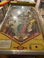
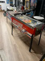
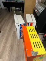
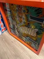
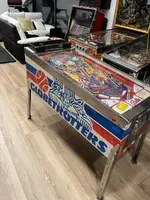
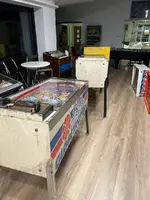
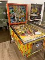
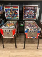
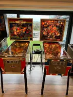
I did a straight swap for my refurbed 8 ball deluxe for 3 games in working condition, but need work:

1. Harlem globetrotters
2. Night Rider
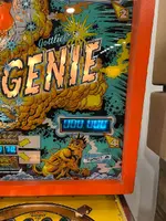
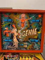
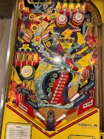
3. Genie
IMG_1449.webpIMG_1450.webpIMG_1451.webpIMG_1454.webpIMG_1453.webpIMG_1452.webpIMG_1455.webp

Aim is to get all 3 up and running and 100% working and playable

Got a league meet to host 9th Feb, so will aim for that as a deadline date.

Night rider has a brand new for backglass which is very nice.

Hgot, only has a translate, but it’s ok.

Genie backglass is original and in good condition but the colors have faded somewhat.

I get the 3 put back together and wired up. They all boot. Night Rider doesn’t have a mains on off switch, it’s been bypassed for some reason! One for the to do list!

I’ve never owned a Gottlieb so I decided to start on genie.

After a few hours of looking into the issue of only one credit, I deduced the 5101 ram chip is duff, so a new one on order.

One of score displays is duff, but it came with 3 spare -but 2 are dead and the third works a bit but then throws a wobbler. I’ve ordered new driver chips - see if I can repair any of these.

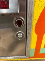
Fixed the non working self test button. Coin door wiring has been cut and it was rejoined incorrectly.

Lots of lamps out and switches not working……….
 
IMG_1464.webpIMG_1465.webpRealised I had the wrong legs on the games, so swapped them about and then realised they’re wrong legs mainly anyway.

Genie got 27” legs which I think are correct for it.

That left me with one set of 28” which is correct for bally, and one set of 31” which are too tall for Bally. So I put the 31” on the rear and 28 on front for both hgot and night rider.

The legs are bent and manky, so I’ve ordered brand new sets from pinball mania. I just hate crap legs.
 
IMG_1460.webp
IMG_1459.webp

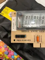
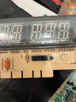
Player score display unit is very simple component wise. I guess those high voltage driver chips either fail, or the display it self gasses-Out. The driver chips are still available, and quite cheap (unlike the Williams driver chips which are rare and pricey). I’ve got 4 faulty score displays, so worth a try to fix them. I’ve also seen that there are led replacements available too.
 
Dunno. I have two dead ones and 2 ones with digits or segments on all the time.

It won’t take me long to remove the two driver chips and install sockets for new ones, so worth a go.

The good news is that the small 4 digit CMBIP display is working perfectly.
 
View attachment 269700View attachment 269701Realised I had the wrong legs on the games, so swapped them about and then realised they’re wrong legs mainly anyway.

Genie got 27” legs which I think are correct for it.

That left me with one set of 28” which is correct for bally, and one set of 31” which are too tall for Bally. So I put the 31” on the rear and 28 on front for both hgot and night rider.

The legs are bent and manky, so I’ve ordered brand new sets from pinball mania. I just hate crap legs.
I'm interested in the 31" legs if they are usable6
 
Genie is playing pretty well now. Needed a few hours work:

- quite a few switches were not working - all needed adjusting. Also a 10 point switch was stuck on - took a while to figure out which one as they’re all connected together

- replaced coin door lock, as there was no key for the original.

- many lamps were out, mostly blown bulbs, but a few down to old dodgy lamp holders.
Looking at the schematics, I think my Ledbars will work as a much more solid replacement, so I will try one later.

I got a bit frustrated with the inbuilt self-test. It only tests the controlled lamps for a few seconds, then moves on to other tests, I couldn’t figure a way to keep it on the lamp test. Anyhow a much quicker way to test controlled lamp’b socket and bulb on this game (and in the bally SS games) is to clip a croc clip wire to Ground somewhere, then ground each lamp sockets centre tab. If the bulb and socket are good, the lamp will illuminate.

Now to play test a few games and see how it all goes!
 
I’ve got 4 faulty score displays, so worth a try to fix them.

I forgot to say that it's best to check the rear nipple, if it's broken then they're useless...! If it has a cover on then leave it on.

Oh and replace the orange cap next to the BR's in the cabinet. Add the required earths and I suggest you chuck the original PSU in favour of a modern one if you're not buying a pascal MPU.

Try the freeplay option to see if you get more than one credit. https://www.pinwiki.com/wiki/index.php/Gottlieb_System_1#Setting_up_a_Game_for_Free_Play

Info on all things display wise, including rejuvenating the displays: https://www.pinwiki.com/wiki/index.php/Gottlieb_System_1#Display_Problems
Thanks Peter - I did the freeplay mod and that works - it still only clocks up one credit, but now of course it immediately adds a player, so it has the desired effect.

The PSU tests out good with all voltages correct and little a/c ripple on the DC's.
 
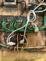
looking at that golbtrotters rectifier board lash up,I guess the previous owner did that themselves?,or did they pay a so called "professional" to repair it?
 
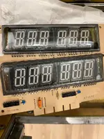
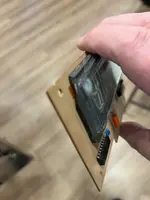
One of the spare displays is gassed out
You can tell because the normally black spots in the corners (top left, bottom right), have gone white. Pic of a good display and the bad one together:
IMG_1473.webp

Oh that’s why it’s lost it’s gas- big piece missing!
IMG_1474.webp
 
Last edited:
Fired up both NR and HGOT. Both boot fine.
IMG_1486.webp

First thing I tried was the self test button on coin door as I find the lamp and solenoid tests really useful to test out a new machine.

HGOT goes into self test just fine. NR doesn’t. I assumed it was the usual wiring or header connector issues from the self test button to the mpu & sdb. ( the self test button is j3-pin1 on mpu but is grounded on a ground wire that comes from the solenoid board). All wiring is ok.
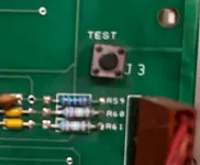
I then noticed a self test button on the actual mpu board. This is a euro dash board. HGOT’s pcb button works fine. NR’s doesn’t

Hmm.
IMG_1482.webp

R59 is present on HGOT but it’s completely missing on NR!!!!! Never been soldered in!!!!! WTF!

As a test I grounded the other side of the resistor pad and Sucess! The game now goes into self test.

Plenty bulbs out on both. A Quick Look under the playfields and it’s the usual
Combination of blown bulbs and dodgy old lamp sockets. Long term I’ll eradicate all these issues with Ledbars, but for now I’ll just fix em up as best I can

Also noted some closed rollovers on HGOT - need adjusting.
IMG_1479.webp

Nice to see some new parts on the two left flippers. Switches and pawls replaced. Right hand one is original
IMG_1480.webp
 
Free play mod on Genie.

I like to put in crock clip wires for free play mods, so it is easily reversible.
This works by making the start button add a credit as well as starting a game. Simples.
IMG_1471.webp

It’s strange to see the switch diodes on a separate board. Bally/stern games have them in the actual switches.

This game also uses germanium diodes not the usual silicon diodes (apparently they won’t work if you put them in as replacements - I guess because they have a bigger forward voltage drop?).

Pic of the hacked coin door wiring
IMG_1472.webp
It’s not pretty but it’s all correctly connected up now. (It can’t before and the self test button didn’t work).
 
HGOT and NR:

1. Replaced blown light bulbs and tweaked dodgy lamp sockets to get all the controlled lights working on both games

2. The apron on HGOT loose at the front:
IMG_1484.webp
IMG_1485.webp
Yes, the metal tabs are missing on the playfield to secure the apron front. But! I saw them in a box of bits that came with the games, so these will be refitted.

3. Cab base of HGOT is filthy:
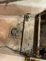
IMG_1481.webp
Will clean it up at a later date.

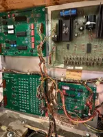
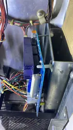
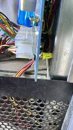
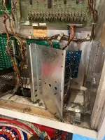
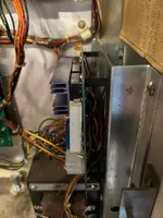
3 New boards in the backbox. They all need re-securing to the back plates
IMG_1483.webp

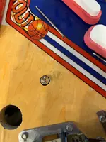
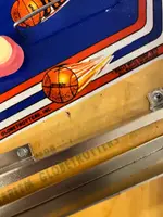
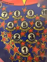
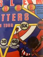
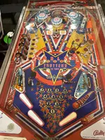
Playfield has had an overlay fitted, but unfortunately the numbers on the inserts underneath weren’t sanded off, giving a fuzzy duplicated effect on the numbers / letters of most inserts. Also the sunken inserts weren’t raised so they are still cupped, but the overlay helps a bit.

I’ll leave this as is for the time being. I’ve got a spare HGOT playfield with a new overlay applied. (It also has a minor flaw, but is much better than this one), so may swap in future.

IMG_1468.webp
IMG_1467.webp
IMG_1466.webp
 
That's 3 houyrs of my life I'll not get back. Strange happenings on HGOT. I got all the lamps working and they all now work in the lamp self-test. So I decided to test play a game. First thing I noticed was that the
5 orange lights opposite the 5 left hand stand up targets were misbehaving. Or rather one was they are all supposed to be lit to start and they go out as you hit their respective stand up. One wasn't lighting.
At first I thought it was a dodgy socket, but as soon as I went back into lamp test - it came on?
Then I noticed some other issues - the spinner lights are supposed to light in sequence on each turn of the spinner - but they seemed out of sequence and one set was on all the time. I thought the usual blown SCR, but again in
the lamp test, they all went on and off as they should do.
As I looked further round the playfield I noticed other oddities :
The credit lamp in the apron wasn't on - it should be when a game is on free-play.
The Special light was permanently lit - it shouldn't be on until that feature is made.
The 8 bonus light didn't illuminate in attract mode when the other bonus lights sequence on and off.

I checked under the playfield to ensure each lamp had the correct colour control wire - these are detailed int he manual. All were correct.

Then I had a suspicion: the lamp driver had two re-pinned connectors - the big 28 way ones. Hmm.

Yep: The wires were in the wrong positions for 6 circuits. Again the manual details what should go where.
I re-did them and now all is good. Phew!


Sorted out the locks on the coin doors for HGOT and NR - the key couldn't be removed when the door was locked, only when it was unlocked. Simple case of rotating the lock catch 90 degrees to reverse the action.

Feel like I'm getting there with these games.

I've got stuff to do to get them fit for a league match, and then other stuff to do once the league match is out of the way.
 
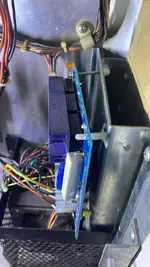
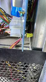
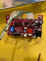
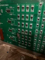
I just couldn’t leave the rectifier board mounted as it was. I.e.:
042296FF-C43D-443D-BFF1-788634E7837F.webp
01BBECA6-A22C-45BE-82C2-515C5AE93A02.webp

Took all that out and removed to transformer and mounting to get to the rear of the pcb mounting plate
IMG_1525.webp

Added some new plastic standoffs. Now all looking good 👍
IMG_1527.webp
 
Whilst play testing I noticed the 2 outer pop bumpers were lit all the time, they are supposed to alternate with the centre pop every time the ball lands in the top saucer (or hits a switch up at the top). The centre pop is going on and off ok.

A Quick Look under playfield and I saw the problem immediately. The ground control wire was soldered direct to ground !!!!! So that’s why they are on all the time.

I desolderec and tried again, no lights at all now!

The game has a new lamp driver board, so I first suspected the connector to the lamp board, but that tested out ok.

Whipped the lamp driver board out and sure enough the scr is blown. Cut the old one off and soldered in a new one. The pcb has holes to allow through hole replacements rather than replacing with SMD. Looks a bit odd, because the through hole is mounted upside down. Also all the through hole holes are filled with solder, so not as easy as just inserting the new component and soldering up, the holes need cleaning out first.

All working now.

IMG_1526.webp
 
Back
Top Bottom