What's new
Pinball info

Register a free account today to become a member! Once signed in, you'll be able to participate on this site by adding your own topics and posts, as well as connect with other members through your own private inbox!

WPC Dot Matrix Controller Board replacement now in production

cwispy

Registered
Joined
Nov 2, 2021
Messages
10
Location
Perth
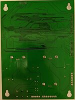
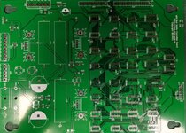
Thought you may like to know that I have been working on making a replacement WPC Dot Matrix Controller Board. I have received the first lot of prototype boards and have found and resolved a few problems already. With a little luck, there will not be any more issues and once testing is complete I will be getting a production run of the boards. The price is going to be approximately $200 AUD.
wpc_controller_board.jpg

Apologies if I have posted in the wrong place or if this is against the forums rules in any way.

cwispy
 
Nice work! They're looking great. I guess with all the SMD components you're planning on getting these assembled?
 
Not sure at the moment if I will invest in a pick n place machine or get these made by someone else. I already build a few other arcade related boards so a pick n place would come in handy, just expensive and takes up quite a bit of space. :)
 
I got a prototype board assembled and was able to test it tonight. The good news is that it did not go bang! The bad news is that its displaying garbage on the display at the moment. So I have to work out what mistake(s) I have made before I can get the final production run under way. Hopefully I will find the fault before the xmas break. 🙂
 
I found and fixed the issues with the board and have it running on test now and its working perfectly. So I will hopefully have some boards ready by about mid to the end of January. :)
 
Would you provide a low voltage only board for use with Pin2DMD etc ?
 
Would you provide a low voltage only board for use with Pin2DMD etc ?
I will have to have a think about that one. I designed these to be a direct drop in replacement, but with some of the original faults resolved so they do not burn out like the original ones do.
 
Very cool project.

I would also ask if a simple DC-DC power converter could be included - with 12V and 5V coming through. As Nutty says - this would be really helpful to install all modern colour DMD's. I think the Original DMD controller had 18V DC already to power some of the IC's - not sure if your board has the same power requirements, and how much grunt they would provide.
The power supply section on the board is identical to the original, with the +5v, and +12 which come from the power driver board. The +62, -113v and -125v DC. which are generated by the onboard. All of these voltages are then passed through to the original display board, but the original vfd only needs the 5v for the ttl and the 12v for the display driver chips. I would not try to run a DMD from these rails as its likely to pull the rest of the logic rail down causing the system to become unstable.
 
I will have to have a think about that one. I designed these to be a direct drop in replacement, but with some of the original faults resolved so they do not burn out like the original ones do.
Which original fault specifically @cwispy ?? I'm rebuilding a few of these, and any info on the weak spots of these is appreciated so the originals can be "more Bulletproofed"... :)
 
Which original fault specifically @cwispy ?? I'm rebuilding a few of these, and any info on the weak spots of these is appreciated so the originals can be "more Bulletproofed"... :)
You cant really do much with the original boards. The high voltage section is poorly laid out which is why they burn so badly. The main issue is the transistors and 5W resistors are too close to each other and the heatsinks should be better quality and further apart.

The best thing to do when repairing them is to locate the 5W resistors as far away from the PCB and transistors as you can.
 
I have received the first delivery of blank pcb's and assembled and tested the first one. It is working perfectly. Starting tomorrow I will be assembling what I can with the parts I have left which will be about 8 more boards. :)
I will be ordering later in the week, so the next lot will probably be about 2 weeks away.


WPCDMCF.jpg WPCDMCB.jpg
 
Back
Top Bottom