Ive got a Williams System 7 (Barracora) and activating any switch on Columns 5 and 6 (From the switch matrix in the manual) activates every switch on the same row that I need a bit of advice about.
Ive removed the switch connectors and ran a jumper cable from column 5 and then 6 to one of the rows and it does the same so dont think its a playfield issue, didnt try with columns 7 or 8 as they are not used on this game
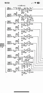
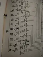
I was looking at the schematic trying to get my head round how it works and what the issue could be and think since its the same on Column 5 and 6 and they both share a Hex inverter that it could be the hex inverter at fault, columns 1 to 4 work without issue and only trigger the jumped row.
I havent tested with a logic probe yet but just wanted to use the hive mind of knowledgeable repairers to see if I have this theory correct.
From looking at the schematic am I right in thinking that each columns output from the board has a pull up resistor so should be HIGH when the column is not activated and then when activated by the MPU it should go LOW, and the reverse coming out of the PIA since there is a HEX inverter inbetween, and that something is causing the column to always be LOW so it triggers all the switches in the row even and not just when the correct column is strobed.
So with my logic probe if its the Hex inverter at fault I should see that the output for the that columnsis always LOW but the inputs should be switching between HIGH and LOW when I'm in switch test, and if its the PIA at fault then the inputs should always be HIGH, is that the correct theory?


