Pinball info
You are using an out of date browser. It may not display this or other websites correctly.
You should upgrade or use an alternative browser.
You should upgrade or use an alternative browser.
vector solenoid
- Thread starter rockhouse
- Start date
I have had this sort of problem on my same era fathom. There is no harm replacing the diode on the solenoid and also the corresponding power transistor, diode and resistor on the solenoid board
Sorry to be so unscientific but these components cost pence so it is easier to replace them than do loads of messing about
You might hit lucky and get a quick win
Sorry to be so unscientific but these components cost pence so it is easier to replace them than do loads of messing about
You might hit lucky and get a quick win
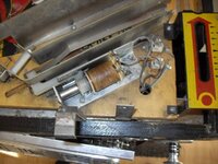
 the one where the ball drains its marked at -27- 1300
the solenoid has 3 connections but only 2 being used
it also has a diode from the left to the middle and a diode from the right to the middle
but only the middle and outside had a connection picture added if my ramblings don't
make sense i thought 3 connection coils were for flippers?
Last edited:
I have had a look at mine. Very hard to take a good pic for you as i have to go through the coin door as game is burried in my workshop
This is the ball kickout solenoid to the shooter lane so should not be hot or get hot as it is very rarely fired
If your game has, or had the wrong fuse in the past (which is very likely), it could have fried this coil. If the coil is fried its insulation on the windings will have perished and resistance will be massively reduced, so the current going through it massively increased, so it will work like a heater. If you look at your coil and my original coil, it looks like yours had been very hot/ burnt out in the past.
If it is burnt out, the coil wont have the power to operate the solenoid plunger so the game may keep sending power to it until it kicks the ball as registered by the ball trough switches. So the coil might be left energised all the time, hence why it is getting hot. You can test with multimeter seeing if it has volts across it. Move ball into shooter lane manually. Then see if the coil still has voltage across it
It would be worth removing this coil from the circuit and testing the resistance of the coil, and comparing to a known working 27 1300 to see whether the insulation is indeed perished
Most likely original cause of this trouble here is dead/ dying power transistor, relevant diode or relevant resistor on your solenoid board.
You have to be very careful with the diodes on solenoid terminals (pegs in my language) on vector (learnt to my cost on fathom) as the solenoid expander board used in these games causes havoc firing 2 solenoids simultaneously if you or someone has removed diodes/ put in wrong way round/ or damaged diodes exist across the solenoid terminals
Grey red wire on mine is middle peg of the solenoid coil. Also on the middle peg is a diode connected to the peg nearest the coin door. The banded end of this diode is on the peg nearest the coin door
Grey white wire is on the peg nearest the backbox. Also on this peg is a diode connected to the peg nearest the coin door. The banded end of this diode is also on the peg nearest the coin door
So both Diodes banded ends should be soldered to the terminal nearest the coin door. There is no "wire" soldered to the terminal nearest the coin door, just the two diodes and the windings of the coil
27 1300 is the correct coil
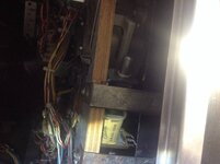
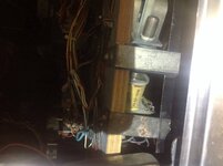
These are taken through the coin door, so you can see where the diodes should be and where the wires should be


Sent from my iPad
This is the ball kickout solenoid to the shooter lane so should not be hot or get hot as it is very rarely fired
If your game has, or had the wrong fuse in the past (which is very likely), it could have fried this coil. If the coil is fried its insulation on the windings will have perished and resistance will be massively reduced, so the current going through it massively increased, so it will work like a heater. If you look at your coil and my original coil, it looks like yours had been very hot/ burnt out in the past.
If it is burnt out, the coil wont have the power to operate the solenoid plunger so the game may keep sending power to it until it kicks the ball as registered by the ball trough switches. So the coil might be left energised all the time, hence why it is getting hot. You can test with multimeter seeing if it has volts across it. Move ball into shooter lane manually. Then see if the coil still has voltage across it
It would be worth removing this coil from the circuit and testing the resistance of the coil, and comparing to a known working 27 1300 to see whether the insulation is indeed perished
Most likely original cause of this trouble here is dead/ dying power transistor, relevant diode or relevant resistor on your solenoid board.
You have to be very careful with the diodes on solenoid terminals (pegs in my language) on vector (learnt to my cost on fathom) as the solenoid expander board used in these games causes havoc firing 2 solenoids simultaneously if you or someone has removed diodes/ put in wrong way round/ or damaged diodes exist across the solenoid terminals
Grey red wire on mine is middle peg of the solenoid coil. Also on the middle peg is a diode connected to the peg nearest the coin door. The banded end of this diode is on the peg nearest the coin door
Grey white wire is on the peg nearest the backbox. Also on this peg is a diode connected to the peg nearest the coin door. The banded end of this diode is also on the peg nearest the coin door
So both Diodes banded ends should be soldered to the terminal nearest the coin door. There is no "wire" soldered to the terminal nearest the coin door, just the two diodes and the windings of the coil
27 1300 is the correct coil
These are taken through the coin door, so you can see where the diodes should be and where the wires should be


Sent from my iPad
