What's new
Pinball info

Register a free account today to become a member! Once signed in, you'll be able to participate on this site by adding your own topics and posts, as well as connect with other members through your own private inbox!

Testing 520-5252-04 out of machine

Paul

Staff member
Joined
Oct 5, 2012
Messages
12,207
Location
South Wales
Friend has sent me a stern opto-interrupter to take a look at because it was not working (Opto issue).

I have replaced the Opto, however i'm trying to work out how to test this out of the machine.

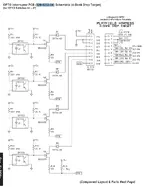
Gnd and +5v i can supply from my bench supply, however it doesnt seem to be doing much. I'm interested (looking at the Circuit diagram - attached) to work out what the STB pin on the connector is expecting...

Anyone tried this and can advise please?
1745051065947.webp
 
Think i may have got it now...

So - BSS123 is a mosfet - So looking at the above, when the Opto is triggered then that allows whatever is connected at the switch input to then be outputted to STB (Cant be the other way as the 4148 would block it).
All the opto does is to provide the +v to the Mosfet to switch it on...

If thats the case, +5v and Gnd to power the beast... then say +5v onto the SWx input... meter between GND and pin 9... which should read circa 5v when the opto is broken...

Sound about right?
 
Paul,

Going by my rusty electronics knowledge, I'd expect the base gate (told you I was rusty) pin of the relevant transistor to change its logic state when the opto is interrupted, switching the device and making/breaking the connection between STB and the SW pin.

The wiring colours shown on the drawing suggest that STB is a switch matrix wire, common to the four optos, which would make the 'Tan-xxxx' wires the switch returns, and the diodes the equivalent of diodes on ordinary playfield switches.
 
Last edited:
Going by my rusty electronics knowledge, I'd expect the base gate (told you I was rusty) pin of the relevant transistor to change its logic state when the opto is interrupted, switching the device and making/breaking the connection between STB and the SW pin.
Exactly what i was trying to say - thank you :) .... The Gate needs to have a voltage applied (From the opto side) and then when it is this "connects" from the source to the Drain..
 
Back
Top Bottom