For some reason both the sound and in game lights i.e special, times up etc aren't working. Checked that there's power to the boards and taken connectors on and off. That's the extent of my expertise so replace a board, another visit to pinball mania to fix or any ideas from you guys?
Pinball info
You are using an out of date browser. It may not display this or other websites correctly.
You should upgrade or use an alternative browser.
You should upgrade or use an alternative browser.
Space invaders
- Thread starter Paulf
- Start date
A bally can play dead if there isn't the right number of balls in it or of the ball trough switch(es) are faulty
Has anything changed ?
ie - have you moved it ? Removed the ball ? Undertaken a repair ?
Did everything work before these symptoms ? Does everything else work now ? Flippers ? Solenoids? Switches ? Score boards ?
Has anything changed ?
ie - have you moved it ? Removed the ball ? Undertaken a repair ?
Did everything work before these symptoms ? Does everything else work now ? Flippers ? Solenoids? Switches ? Score boards ?
Sound and special lights not working ??
Do you mean the flashing lights ? ie attract mode !
Open backbox and switch game on and count how many flashes on the mpu that's the board on the top left !
Do you mean the flashing lights ? ie attract mode !
Open backbox and switch game on and count how many flashes on the mpu that's the board on the top left !
It was moved (house decorating) and then put back. Worked for a while but then had couple of instances of what can only be described as "power surges", lights going very bright and louder (than usual) buzzing. Worked again after this then died. Everything else works, there's only one ball so so shouldn't be an issue. The mpu flashes are right. Have the original manual but in the problem solving section their answer is just to replace various boards!
In your shoes I would investigate all fuses and voltages first.
There are various "touch points" on the circuit boards that enable you to test DC and AC voltages. The manual will show you where and what voltages are.
My vector failed suddenly and it was an old bridge rectifier that had died.
Report back when you know that voltages and fuses are OK.
If so, next point I would investigate is dirty connectors and header pins for cold joints.
Others on here know better than me precisely where to look
as above check all fuses on power supply rectifier board and then measure all the test points to ensure the dc and ac voltages are correct as per the manual/schematics
also try the self tests using the inside coin door red button, test 1 is all to flash all lamps on off, are they all out or only certain ones.
there is also a sound tests in the self tests, do you get any sounds in the test?
Worrying that you had an issue recently with lights being very bright. that indicative of over voltage so as previous poster has said could be a failed or failing bridge rectifier on the rectifier board, hence need to test the voltages are correct
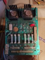
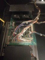
So, tested rectifier and all OK apart from tp4 (general illumination) should be 7.3 vac however barely registering. Now when I took the plastic cover there was a bit of solder just lying on the board near the fuses (about 1.5cm). As all the parts are original I don't know if this was supposed to do something or had just fallen from the bottom of the playfield (lots of stuff been soldered). I've attached pics for a, spot if anything is obviously wrong challenge.
So final question is, is it knackered? If so should I be looking at that specific rectifier or is there an alternative.
As always thanks for any info.
So final question is, is it knackered? If so should I be looking at that specific rectifier or is there an alternative.
As always thanks for any info.
Attachments
This video shows you how to test your bridge rectifiers with a meter
Check that the Bridge has failed rather than it just being a dry joint.
Pinball heaven and pinball mania sell Bridge Rectifiers if you need one. On ebay, Farnell, other pinball suppliers..
Check that the Bridge has failed rather than it just being a dry joint.
Pinball heaven and pinball mania sell Bridge Rectifiers if you need one. On ebay, Farnell, other pinball suppliers..
did you test using your meter on ac setting or the dc setting?
ps if all the other dc voltages are ok then it’s probably not the rectifier board.
Had to double check myself lol !!well spotted Carl,I missed that
^ Yes well spotted.

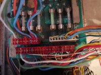
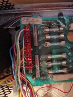
You J3 Pin8 looks toasted. Is a good idea to change that connector with a newer trifucton pins and connector.
TP1 is ok?
TP4 Cames directly from the transformer. TP4 is an AC voltage that doesn't get converted to DC, and hence doesn't have a bridge rectifier.
have you put your meter on AC to measure tp4 ?
also have you run the tests by pressing the red button inside the coin door? what happens for each of the tests.
also have you run the tests by pressing the red button inside the coin door? what happens for each of the tests.
You were right about ac setting. Coming out at 5.7v for tp 4. Attached video of switch on. Not getting lamps switching on/off or for test 4 the sound. Sometimes when it's switched on and off there's a very brief bit of sound. Also attached the video of self test of mpu for stuck contacts although had to do this quick because of video size limits.
Attachments
The general illumination bulbs are there. Seems you have a problem with the cpu controlled lamps. But all of them seems to be off. Check the TP1 and the F1 fuse.
couldn’t really make out the videos. so when you switch on do you get all the GI lights on? or non or only part?
if you then go into the test menu , test 1 should flash on and off all the controlled lamps? do any flash or all or non?
You have controlled lamp problems and no sound. that suggests an issue with the mpu board or with the wiring from the mpu board. check the connectors are good especially the top left to mpu board this has the lamp data. it also has the score display data but that looks ok? Another issue could be the lamp driver board has blown.
obvious question. have you changed the bulbs to rule that out?
J3 pin 16 on the solenoid drive board powers the lamp driver board on J4 pin 3 it's the black green wire (84) could be a bad r broken connection here ? Take off said connections and tickle with a bit of sand paper on the male pins and reconnect . Do you have power on lamp board ?
On the sound board do the same remember you should be able to see the 3 male pins on the right when the connector is connected on the board , also I take it the speaker wire is connected up ?
On the sound board do the same remember you should be able to see the 3 male pins on the right when the connector is connected on the board , also I take it the speaker wire is connected up ?
The lamp driver showing 5v at tp1, aux 5.3.
The one thing I can see is sound board tp1 is 1.3 should be 11.9 and tp4 should be 2.5 and is 3.9.
Checked wire 84, took off and reconnected.
On this sound board as-2518-51 only 2 male pins for sound.
The one thing I can see is sound board tp1 is 1.3 should be 11.9 and tp4 should be 2.5 and is 3.9.
Checked wire 84, took off and reconnected.
On this sound board as-2518-51 only 2 male pins for sound.
Well, your J3 Pin8 in your rectifier board is toasted. Also, those IDC connector are not very reliable. The J3 Pin8 in the rectifier board (toasted in your pics) send 12VDC to the soundboard. Check the connector, check the probably toasted cable/connector. Check if you have 12v in J3Pin8 in the rectifier board. I you dont have it there, the bridge rectifier should be replaced. Good luck
If one of the rectifier boar pin is toast like in your pics, that is a signal that you should change the pins and the connector for more robust ones.