simonlindsay
Registered
Hi,
I have removed Ted's head, not for the first time but hopefully the last!
Basically, none of the eyes or lids are working on both Red and Ted. I did replace the SM 31-900 a few years ago in Ted's head (all eyes and lids worked except lids in Ted's) but when I switched the machine on, it started to smoke at the back of the machine in the Ted head vicinity. So I left it switched off for 7 years (too scared to switch it back on) and switched it back on a few months ago - everything worked on the machine except none of the eyes or lids on either head.
I removed Ted today and saw the lid coil was solid. I have not stripped the head completely as I wanted to clarify some points, so here goes...
I have attached photos to try and explain.
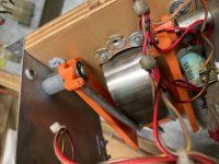
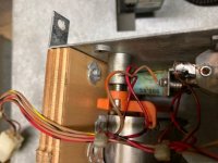
Firstly, is the coil in the right way? The plunger appears to be solid so I figure it has burnt out
Should the two wires (Brown/Red) go to the lug where the plunger is? And should the single Red/Black go to the bottom end of the coil? As per the pictures. Or is it the other way round?
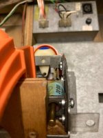
I believe the coil is missing the centering flange ( I ordered one on the off chance it was missing) and assume it goes between the coil and the end plate.
The brass 'pawl' seems to be sticking out of the hole in the bottom - is this correct? I looked at the bottom of Red's head and it looks the same.
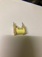
On the photo with the new coil, does the 'lip' go to the plunger or is it the flat bit on the end. Depending on this answer, will determine what to do with the wiring and which lugs the wires go to.
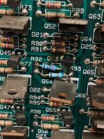
Once the replacement coil is in place and correctly wired, should I check transisitors or anything else?
Sorry for the long post and the many questions but I don't want the machine to smoke or burst into flames and not be able to play it for another 7 years!!
Thanks in advance.
Simon
I have removed Ted's head, not for the first time but hopefully the last!
Basically, none of the eyes or lids are working on both Red and Ted. I did replace the SM 31-900 a few years ago in Ted's head (all eyes and lids worked except lids in Ted's) but when I switched the machine on, it started to smoke at the back of the machine in the Ted head vicinity. So I left it switched off for 7 years (too scared to switch it back on) and switched it back on a few months ago - everything worked on the machine except none of the eyes or lids on either head.
I removed Ted today and saw the lid coil was solid. I have not stripped the head completely as I wanted to clarify some points, so here goes...
I have attached photos to try and explain.
Firstly, is the coil in the right way? The plunger appears to be solid so I figure it has burnt out
Should the two wires (Brown/Red) go to the lug where the plunger is? And should the single Red/Black go to the bottom end of the coil? As per the pictures. Or is it the other way round?
I believe the coil is missing the centering flange ( I ordered one on the off chance it was missing) and assume it goes between the coil and the end plate.
The brass 'pawl' seems to be sticking out of the hole in the bottom - is this correct? I looked at the bottom of Red's head and it looks the same.
On the photo with the new coil, does the 'lip' go to the plunger or is it the flat bit on the end. Depending on this answer, will determine what to do with the wiring and which lugs the wires go to.
Once the replacement coil is in place and correctly wired, should I check transisitors or anything else?
Sorry for the long post and the many questions but I don't want the machine to smoke or burst into flames and not be able to play it for another 7 years!!
Thanks in advance.
Simon
Attachments
Last edited: