What's new
Pinball info

Register a free account today to become a member! Once signed in, you'll be able to participate on this site by adding your own topics and posts, as well as connect with other members through your own private inbox!

Mr & Mrs pacman pinball display problem?

Martin.D

Registered
5Years
Joined
Jul 28, 2019
Messages
159
Location
Bromley, Kent.
Wonder if anyone can shed some light on this odd problem with new displays for Mr & Mrs pacman pinball.

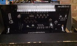
When all 4 displays plugged in Player 2 & 4 show 6 zeros (See (Bad) picture) and do not increase score when playing.
But Player 4 score showing 6 zeros with figure 7 (Last on left of display) flickers 0 when playing.

More investigation plugging only Player 4 cable into Player 3 display game shows Player 4 scoring normally.
Plugging Player 3 cable only into Player 4 display displays 6 zeros.

Do not think anything wrong with displays, maybe cable or power?
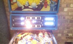

DisplayStart.jpg

DisplayBoard.jpg
 
Upgrading a Bally like this to leds is very dependent on how good your +5v is coming from the solenoid driver board. If you think about it, the 5v now has to provide a lot more current to illuminate the leds on the score displays whereas before it was powered by the high voltage supply for the original gas plasma score displays. So, make sure you have a good 5v supply and connectors and headers are good, also make sure you have good connection from the mpu board to the score displays. (top left connector on the mpu board ) again repin the header and connector if it’s dodgy

If you have the original displays switch them all back in, prove it works, then try swapping in one led displays at a time. it could be a faulty one.
 
ps i’ve had the same issues occasionally with my machines and my own made led displays. almost all of the time it has been dodgy 5v, or bad connectors.
 
Upgrading a Bally like this to leds is very dependent on how good your +5v is coming from the solenoid driver board. If you think about it, the 5v now has to provide a lot more current to illuminate the leds on the score displays whereas before it was powered by the high voltage supply for the original gas plasma score displays. So, make sure you have a good 5v supply and connectors and headers are good, also make sure you have good connection from the mpu board to the score displays. (top left connector on the mpu board ) again repin the header and connector if it’s dodgy

If you have the original displays switch them all back in, prove it works, then try swapping in one led displays at a time. it could be a faulty one.
Thanks for tip. Logical that not enough power could be the source of problem.
Will go over schematics for cable find and test 5v + headers.
 
Cross posting this information as hard figure this problem out when when source of fix is other displays.
Ok first thanks go's to Hop-Pac (Pinside) for walking me through this problem and picture of connectors. And ecto1a2003 (Pinside) for original solution.

Source of problem new LED displays, in this case tested on Pinball Center & Pinscore displays.

From Strange Display Behavior Question [Solved] topic:
"Turns out everything was re-pinned and re-installed properly. But...on the original display IDC connector housings, there were wires that were routed across some of the unused pins. So, for example, a given wire would be daisy-chained (but unused) across two connectors, say, to get to the third connector where it was used. The wire was still inserted into the IDC on the skipped-over displays, but on an unused pin. This didn't cause any trouble on the original displays. On the Wolffpac displays however, this appears to be an issue. At least it is in my game."

From Pinscore Displays MMPM... Fixed! topic:
"Pull the wire out of the IDC connector at pin 11 on the score displays . Do not cut the wire. Just pull it out."
Note pin 11 pulled on displays 1 to 3, 4 does not use pin 11.

Fixing the problem all displays now running.
All praise the power of the forums:clap:
 
Aha, nice find. Pin 11 often connected to pin12 which is used, so that would drive it crazy. Pin 12 is the 7th digit enable pin. So you'd get all sorted of weird stuff showing up.
 
This is a nice find, and it’s good to find the cause of this weird display problem

So what signal is actually being routed through the ‘unused’ pin11 on the cabling and why is there a difference to the original displays???
 
This is a nice find, and it’s good to find the cause of this weird display problem

So what signal is actually being routed through the ‘unused’ pin11 on the cabling and why is there a difference to the original displays???

Having first started with suggestion on this forrum on voltage and continuity test this was odd problem when all tests came back ok.

Not sure what signal is being used, but pin 11 wire colour on display 1 & 2 is different to wire colour on display 3. ALL have to be unpinned for display 3 & 4 to work.
So not 1 problem but 2. Guess one jams the other? As for what pin 11 is Manual & Schematics are unhelpful in that regard.

I assume new LED displays designed for more pinball tables to use and as original forum topic talks about being less tolerant.
Hmmmm, would be interesting to know the wire colours and where they route to on the cpu j1 connector for understanding
 
Last edited:
Wire colours Display 1 & 2 (Player 1 & 3) pin 11 wire Yellow with red stripe. Display 3 (Player 2) pin 11 Brown with orange stripe.
On J1 CPU board Yellow with red stripe pin 21 & Brown with orange stripe pin 23.
 
Wire colours Display 1 & 2 (Player 1 & 3) pin 11 wire Yellow with red stripe. Display 3 (Player 2) pin 11 Brown with orange stripe.
On J1 CPU board Yellow with red stripe pin 21 & Brown with orange stripe pin 23.

Ok so as suspected these are the unique display latch strobe wires. What a bizarre idea to route through other connectors unused pins!! Must have been the easiest way for the cable manufacturing at the time. Every day is a school day, even after 30 plus years!!

So if on some other games or maybe on stern games? pin 11 is tied to pin 12, the led display replacements should really have a solder jumper pad so you can set which config you want. It could also be some error being taken forward from a 6 digit display design as pin 11 and 12 were both unused on those so could have been tied together and to ground ,maybe, for 'neatness'.
 
Knowledge is king, prepaired should this happen again.

Maybe design update needed for LED displays? or at least warning for use with some pinball machines.
 
Somebody has messed with the wiring post factory I suspect
Wiring was original. Maybe this issue only happens on games with the displays altogether below the backglass or pacman only

2 seperate pacmans confirmed as showing the same issue when using led displays

I still don’t understand why some Led displays joined pins 11 & 12 ???
 
Wiring was original. Maybe this issue only happens on games with the displays altogether below the backglass or pacman only

2 seperate pacmans confirmed as showing the same issue when using led displays

I still don’t understand why some Led displays joined pins 11 & 12 ???
11 is joined to 12 to make them compatible with stern machines
 
And in doing so breaks compatibility with some Bally games it looks like. As I mentioned above a dip switches or jumper setting would be better
According to the mrs and mrs pac-man documentation pin 11 is not used , possible a trainee was doing the loom assembly that day 😂😂
 
more like all pac-mans are not compatible!! :)
Sorry Jim, just read those two threads on pinside, deffo seems the pacmans were wired like that in the factory from others experiences, apologies.

Another fix would be to cut off pin 11 on the led display board’s header, a bit easier to do than pulling out wires from the connector housings maybe? The only drawback being that those led displays wouldn’t then work in a Stern machine,m if you ever wanted to move them about, but probably a non issue.

No problem. Yes cutting the pin 11 seems like a better idea seeing as the displays would likely stay with the machine. It makes me wonder how centaur 2 and 8 ball deluxe le are wired up to. I wish that thread on pinside had been around a few years back, these pinball centre white displays I had I nearly smashed the ****ers up more than once!!! As I was saying before, always good to learn/hear about something new tech wise. :)
 
Back
Top Bottom