Well it's Friday night. I am writing this from a dressing room after completing a performance at a 40th Birthday party from some guy called 'Peter' - who to be honest, was a bit weird.... But I digress....
I was in a similar dressing room and browsing few a few forums about addressable LEDs, which I have been experimenting with a lot lately when I had the idea to try this.
After buying a Gozmod saucer - which whilst I think its good - its not the best mod out I had a spare AFM saucer board so I thought I would have a go at doing something with addressable LEDs.
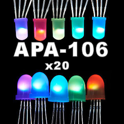
I found these on eBay.

So I had the idea to kind of rip my old board apart and fit these LEDs into it.
KEEP IN MIND - THIS IS A PROTO IDEA so I am not into neatness on this. Just a proof on concept.

I removed the LEDs and 16 resistors, as well as two 2803A chips.
Decided to use the COMMON to each LED as a 0V, and on the back - shorted some of the PCB to give me a +5V leg.

Next up - I modified the LED holders so that the 0V ground and +5V mounted to the PCB. Then the IN and OUT would stick thru the side.


Yes - my hands are filthy - its called graft !")
Okay - next up I soldered in the LEDs

The DATA ins and outs go in Series.
Then I plugged in my Arduino R3. You can get a smaller Arduino to do this.

So basically you feed a 5V power supply into the LEDs and the PCB. The Arduino can be powered down your USB but it wont run the LEDs.
I put in some code.
IT'S ALIVE!!!

SADLY - iPhones are not good at filming these LEDs.
Here is a cack YouTube video.
So - I have a few questions:
1 - Do I build some PCBs to do this properly?
2 - Is it worth pursuing?
3 - Does anyone want to get on board and help out with this. I was going to suggest running some trigger switches on the playfield to change patterns within the game - as the PCB can take triggers via a small interface board.
4 - If I was to make these, what would be a good price? I would also be happy to keep it 'open' for other people to make as well.
Was planning to use the same cable to the existing saucer, but with a break out box in the back box - that would carry the flasher, +5V and ground, as well as any other signals needed.
OR if Jim at MyPinballs wants to make it - I can send this across to him to take it further.
Link to the LEDs on eBay:
I was in a similar dressing room and browsing few a few forums about addressable LEDs, which I have been experimenting with a lot lately when I had the idea to try this.
After buying a Gozmod saucer - which whilst I think its good - its not the best mod out I had a spare AFM saucer board so I thought I would have a go at doing something with addressable LEDs.
I found these on eBay.
So I had the idea to kind of rip my old board apart and fit these LEDs into it.
KEEP IN MIND - THIS IS A PROTO IDEA so I am not into neatness on this. Just a proof on concept.
I removed the LEDs and 16 resistors, as well as two 2803A chips.
Decided to use the COMMON to each LED as a 0V, and on the back - shorted some of the PCB to give me a +5V leg.
Next up - I modified the LED holders so that the 0V ground and +5V mounted to the PCB. Then the IN and OUT would stick thru the side.
Yes - my hands are filthy - its called graft !
Okay - next up I soldered in the LEDs
The DATA ins and outs go in Series.
Then I plugged in my Arduino R3. You can get a smaller Arduino to do this.
So basically you feed a 5V power supply into the LEDs and the PCB. The Arduino can be powered down your USB but it wont run the LEDs.
I put in some code.
IT'S ALIVE!!!
SADLY - iPhones are not good at filming these LEDs.
Here is a cack YouTube video.
So - I have a few questions:
1 - Do I build some PCBs to do this properly?
2 - Is it worth pursuing?
3 - Does anyone want to get on board and help out with this. I was going to suggest running some trigger switches on the playfield to change patterns within the game - as the PCB can take triggers via a small interface board.
4 - If I was to make these, what would be a good price? I would also be happy to keep it 'open' for other people to make as well.
Was planning to use the same cable to the existing saucer, but with a break out box in the back box - that would carry the flasher, +5V and ground, as well as any other signals needed.
OR if Jim at MyPinballs wants to make it - I can send this across to him to take it further.
Link to the LEDs on eBay:
APA-106 Addressable RGB LED 5mm/8mm - like Neopixel (20 Pcs) | eBay
20 pieces of the selected size APA-106. - Nominal power consumption: 0.3W.
www.ebay.co.uk
