What's new
Pinball info

Register a free account today to become a member! Once signed in, you'll be able to participate on this site by adding your own topics and posts, as well as connect with other members through your own private inbox!

Favour from a centaur owner please

Poibug

Registered
10 Years
Joined
Aug 10, 2011
Messages
3,281
Location
flintshire
Could do with two favours please.
When you go into the built in diagnostics tests, then onto the speech.
Does it say power orbs with 01 flashing on the displays?
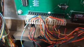
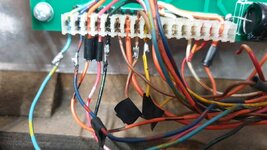
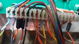
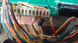
Secondly can ya take a picture of the J1 connector going to the squawk and talk.

Reason is I am trying to make double sure I did This right when I changed it.

I guess it should be of an original centaur, in case the later one was different.

My connector is like this

TIA

Poibug20200513_195053.jpg
 
You only have 16 pin connector not 18? No pictures before you made a new one?
 
You only have 16 pin connector not 18? No pictures before you made a new one?


Exist connector was 1 smaller, it was a 15 pin so it was pointless me cutting off excess off my 16 pin as it's keywayed.
I accidentally deleted the two photos I had!!
 
Last edited:
Hence me asking original question so if someone has a photo of theirs it would be appreciated.
Bally manuals ain't the best, just ok
 
My Centaur came like this ! I am not guilty. No idea what is going on, but it works ....

When the 01 comes up along with the Blp, blp, Blp, blp noise , that is the switch test telling you a ball is in the trough
 

Attachments

  • 20200514_084954.mp4
    20200514_084954.mp4
    18.5 MB
  • 20200514_083505.jpg
    20200514_083505.jpg
    87.7 KB · Views: 37
  • 20200514_083514.jpg
    20200514_083514.jpg
    101.1 KB · Views: 39
  • 20200514_083704.jpg
    20200514_083704.jpg
    84.8 KB · Views: 41
  • 20200514_083713.jpg
    20200514_083713.jpg
    93.4 KB · Views: 37
Ok, based on what David's picture shows and the manual configuration I think poibug's pin 15 should have only 1 Red/Yellow wire connected, with the second Red/Yellow wire going to pin 16.

David's picture shows he has a broken Red/Yellow wire going to pin 15, so he might be missing a few sounds or speech. It could be said that the orange wire in pin 17 shouldn't be there, I wonder if it's pushed in enough to make connection anyhow.
 
  • Like
Reactions: DRD
Thanks all now fixed.
I agree with @Moonraker , 're that extra orange cable and the broken red and yellow cable @DRD

And based on a picture I saw whilst trawling last night, mine is connected right.
Plus I appear to have all necessary sounds and speech right, compared to the emulated one on ps4, as well as others videos of the game
 
Would be cool to be 100% sure if someone else has a picture tho think we're right now
 
  • Like
Reactions: DRD
@myPinballs , do you have a Centaur you could photo pls ?

When we have a definitive snap of what this connector should look like, I will rebuild my game's horror story of a connector.

I was wondering whether that floating wire was something to do with the @myPinballs board ?
 
4347b07798982a75c0f61e301b2b3228.jpg
 
@myPinballs , do you have a Centaur you could photo pls ?

When we have a definitive snap of what this connector should look like, I will rebuild my game's horror story of a connector.

I was wondering whether that floating wire was something to do with the @myPinballs board ?

I will post a pinout guide listing what all 18 pins do later. The board was designed for multiple uses in both pinball and arcade games. Your wiring although done badly has been done to wire up the extra pins which isnt really needed in pinball use. You can see on the pic by andy that the centaur connector is shorter than 18 pins.

And NO the floating wire isnt anything to do with using my boards, what a question!!! You just use the stock connectors like the originals.
 
Also here are some pics of my pacman s&t J1 connector . Same pinout and wires for all s&t games.
The Vector backbox schematic similarly shows 17 of 18 pins in use at A14 J1 when a 15 pin connector is fitted. All the Vectors I've seen have the White/Orange wire jumpering pins 12 and 14 per you doc, but not used on your M&MPM, is the requirement for this jumper machine specific? Thanks.
 
The Vector backbox schematic similarly shows 17 of 18 pins in use at A14 J1 when a 15 pin connector is fitted. All the Vectors I've seen have the White/Orange wire jumpering pins 12 and 14 per you doc, but not used on your M&MPM, is the requirement for this jumper machine specific? Thanks.

The white/orange jumper is to tie the sound select line 5 to ground, as s&t only uses 4 select lines ( 2 lots of 4 bits sent using a specific timing) but i don't actually think its needed.
 
Back
Top Bottom