switched on dr who after it has been stood for about 6 months and was greeted with the factory reset . Batteries are mounted off the board and was using lithium batteries ,so I have no battery leakage. So installed new batteries and setting etc and started play game for a test and that’s when I noticed the expander not working , so put it in test and it still didn’t work . I disconnect the motor,which was nice an easy as it is connected with scotch block , so I then lashed up 12v to the motor to see if it moves and yes it does . The gearbox and motor are working perfectly. Looking at the Bi directional board on the machine and J2-1 and pin 4 are both reading 20v with the game switched on , that can’t be right ? .Tip 107s and 102s read ok ,so now i am a bit stumped !
Pinball info
You are using an out of date browser. It may not display this or other websites correctly.
You should upgrade or use an alternative browser.
You should upgrade or use an alternative browser.
Dr who expander Not working
- Thread starter carl lawrence
- Start date
20V are strange indeed as the board should be supplied with 12V. If the drivers are Ok it should be U1. you can check pins 5-4 and 7-6, they should be driven inverse, i.e. 5 more positive then 4 and 6 more positive than 7. That should create either +12V or -12V to the motor.
Put the playfield in the upright position and test the expander. If it works then you most likely need a new gearbox (normally come with motor fitted).

 www.pinball.co.uk

Dr Who, mini playfield motor & gearbox 14-7970 - Pinball Heaven
Yep I agree as 20v is strange but20V are strange indeed as the board should be supplied with 12V. If the drivers are Ok it should be U1. you can check pins 5-4 and 7-6, they should be driven inverse, i.e. 5 more positive then 4 and 6 more positive than 7. That should create either +12V or -12V to the motor.
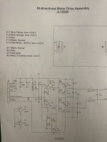
The wording says 20v but the drawing says 12v

I disconnect the wires from the motor and added 12v straight to the motor and it moves up and perfectlyPut the playfield in the upright position and test the expander. If it works then you most likely need a new gearbox (normally come with motor fitted).

Dr Who, mini playfield motor & gearbox 14-7970 - Pinball Heaven
www.pinball.co.uk
This dr who does have a Rottendog cpu unfortunately .
So had the driver board out and checked the tip 102s and they check Ok so will check the U1 @drhex !
So I turn my attention to the motor board pinwik says it could be diode D8 or D9 so unsolder one leg off to check and there are Ok ,next up the cap at C2 so unsolder that and wipe under the cap and refitted and the expander moved up and down and back up and then stopped working again . So unsolder it again and noticed one of the trace is missing so I am need to order a new cap and do some type of repair for the missing trace .
Keep in mind (what has not been mentioned) - you can not test the time expander without:
a: the glass being on
b: the door closed.
c: the balls in the trough (I could be wrong on this one!)
Did you take out your CPU board?
I seem to remember that the switch on the glass on the top left needs to be jammed with some cardboard if you want to test the motor (see point A).
I once had a call out for this very thing not working and all it was the microswitches metal part popped off.....
I fitted mirror side blades a good few years ago and I didn’t want to drill the blades so that switch is taped up .that was my first port of call to check that the switch was still closedKeep in mind (what has not been mentioned) - you can not test the time expander without:
a: the glass being on
b: the door closed.
c: the balls in the trough (I could be wrong on this one!)
Did you take out your CPU board?
I seem to remember that the switch on the glass on the top left needs to be jammed with some cardboard if you want to test the motor (see point A).
I once had a call out for this very thing not working and all it was the microswitches metal part popped off.....

Or with the glass off put the game in expander test, pull the coin door switch to enable power and put both hands on the flippers (no need to worry about glass being on, the coin door being closed or having balls in the game). It will then cycle through the expander test. As previously stated, leaving the playfield in an upright position will confirm if the issue is with the gearbox. They can be a bit intermittent when they first fail but having the playfield in the upright position takes the weight off the gearbox allowing it to operate without slipping.Keep in mind (what has not been mentioned) - you can not test the time expander without:
a: the glass being on
b: the door closed.
c: the balls in the trough (I could be wrong on this one!)
Did you take out your CPU board?
I seem to remember that the switch on the glass on the top left needs to be jammed with some cardboard if you want to test the motor (see point A).
I once had a call out for this very thing not working and all it was the microswitches metal part popped off.....
Was the playfield in the down position or left upright to give you access to the motor?I disconnect the wires from the motor and added 12v straight to the motor and it moves up and perfectly
When I temporarily put 12v to the motor , yes the playfield was up ,and it indeed it moved very quickly with no weight to slow it down . Looking at my the motor and gearbox it does look that it has been repaired in the past as it is not a sealed unit anymore .Or with the glass off put the game in expander test, pull the coin door switch to enable power and put both hands on the flippers (no need to worry about glass being on, the coin door being closed or having balls in the game). It will then cycle through the expander test. As previously stated, leaving the playfield in an upright position will confirm if the issue is with the gearbox. They can be a bit intermittent when they first fail but having the playfield in the upright position takes the weight off the gearbox allowing it to operate without slipping.
Was the playfield in the down position or left upright to give you access to the motor?
I have ordered a new cap so hopefully that will arrive in a few days and when it does I will sort out the missing trace on the board
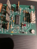
As it should look like this pi takes from pinwik
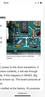
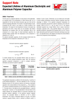
I read that it just smooths the voltage out and wasn’t needed put I wasn’t shore .I will do this tomorrow now after work and see what happens 

Caused by a leaky electrolytic. Starting to happen a lot now they are beyond their "working life"... 
Ironically I was thinking about that the other day , I think I have 4 machines that have caps on them and it going to be a mammoth task to swap them allCaused by a leaky electrolytic. Starting to happen a lot now they are beyond their "working life"...
Okay board trace repaired and the cap not installed , cough !
and the little led on the board seems to be a bit brighter than before but that could be just me
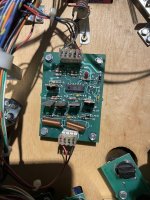
And bingo back working
Big thank you for everyone’s help really do appreciate that !
Ps I have now changed the temp fix with the playfield glass switch , as it is now zipped tied and taped up .
and the little led on the board seems to be a bit brighter than before but that could be just me

And bingo back working

Big thank you for everyone’s help really do appreciate that !
Ps I have now changed the temp fix with the playfield glass switch , as it is now zipped tied and taped up .
I forgot to check that after it started to work again , will check tonight when I get back from work and let you know !Just out of interest, do you have 12V or 20V on the board?
Great it is working again!
J1 pin 5 on board is 22v and J2 drops to 20vJust out of interest, do you have 12V or 20V on the board?
Great it is working again!
So calling anyone who has a dr who can check if they has 20v or 12v that would be great .

