What's new
Pinball info

Register a free account today to become a member! Once signed in, you'll be able to participate on this site by adding your own topics and posts, as well as connect with other members through your own private inbox!

In Progress DE Star wars Project

russdx1

Site Supporter
5Years
Joined
Jul 7, 2018
Messages
3,418
Location
Bristol
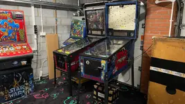
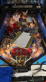
This time we have Tony’s project DE SW to fix! This won’t be a tear down to every last bolt mint restore like ES but basically get the game up and running and into players condition replacing as many broken parts as possible.

The game is quite run down at the moment and will need all rubbers and a large chunk of plastics replacing. But mechanically looks pretty good under the pf.

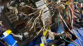
There has been quite a bit of rework in the back box around what I assume is the gi circuits burning out connectors, ending up with cut wires and wires soldered directly to pcbs :( this will get addressed firstly.

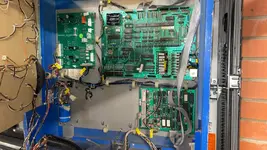
So this is where we are at the moment
IMG_1157.webp

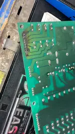
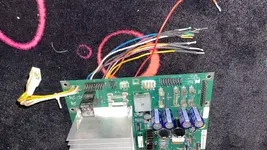
I removed the old power supply board which has had quite a lot of rework and burnt connectors and replaced with a new aftermarket one which Tony supplied with the game.

This is the old one
IMG_1158.webp

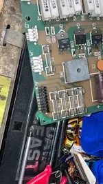
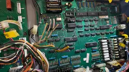
I also remove the ppb board and replaced a bad connector which had wires soldered directly to it (this part of the board is just some fuses, I assume GI?)
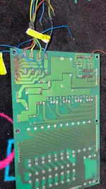
IMG_1159.webp

And afterwards
IMG_1162.webp
IMG_1163.webp

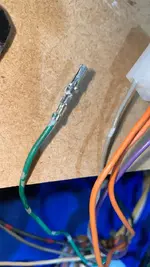
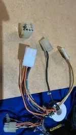
Next step is the power supply loom had a really burnt up connector which I need to replace! (Lucky Tony supplied a new one!)

So I’ll cut the old off and crimp new one on and fix the cut / missing wires.
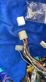
IMG_1156.webp

The PF wire loom also has cut wires / missing connectors but will worry about / replace them later
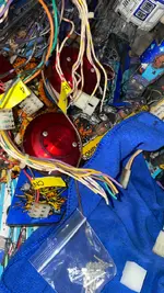
IMG_1160.webp


So my current plan of action is the following.
- replace PPB burnt connector (done)
- replace power loom GI? connector
- plug all power loom connectors into power board (with all other connectors disconnected) and power up game and check power supply board voltages.
- connect back box power loom to other back box pcbs (ppb, cpu, audio, display) and see if the game will boot?
- repair pf loom cut wires / missing connectors
- plug in pf loom switch matrix connectors and see if cabinet / pf switches work? (Go through test menu etc..)
- plug in pf cpu lamp matrix connectors, see if those lamps work?
- plug in pf loom coils connectors, see if coils work?
- plug in pf loom (repaired) GI connectors and see if GI works?

Once got game electrical system fully working I’ll move onto the pf and tear it down a little and start replacing rubbers and any broken plastics / mechs etc.. check switches etc…

Wish me luck!
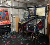
IMG_1151.webp
 

Attachments

  • IMG_1151.webp
    IMG_1151.webp
    134.3 KB · Views: 12
Managed to re-pin the power loom connector.
IMG_1167.webp
IMG_1168.webp

So that’s now good as new! Also added a tiny bit of solder to each crimp to 100% make it’s a solid connection.

I plugged this loom into the power supply board and powered the game up and tested the voltages in the test points and they all looked good. I then plugged in the other boards power connectors and powered up the game and the CPU board legs appeared to light as expected for a booting game.

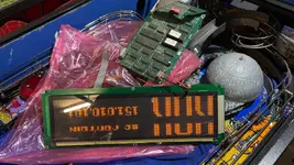
I then plugged in the display board + spare DMD (original has big crack!) and powered up the game and saw a bit of life!
IMG_1169.webp

I see a bit of a boot screen then DMD goes blank, then wait 10sec see the high scores attract mode then it goes blank again…. Then comes back to high scores. It’s like only the high scores part of the attract mode work??? Which is really weird as the rom / cpu is clearly running.

I plugged into the audio to see if I got the boot music and I did!!! So audio is ok. Just this weird display.

Will get the cabinet test switches hooked up next see if I can get more out of the DMD via test menu.

I might then jump to fixing those pf connector hacks as it’s easier to fix whilst loom hanging out machine then all put in place in back box. Need to work out what connectors I need to buy.

Least we saw some life! Which is a good start :)
 
I then plugged in the display board + spare DMD (original has big crack!) and powered up the game and saw a bit of life!
View attachment 268773

I see a bit of a boot screen then DMD goes blank, then wait 10sec see the high scores attract mode then it goes blank again…. Then comes back to high scores. It’s like only the high scores part of the attract mode work??? Which is really weird as the rom / cpu is clearly running.
One of three possibilities:
1. The game is blanking - normally you see all the playfield lights going on and off in unison.
2. The power supply cable is insufficient - normally only seen in games with the larger display. You can buy doubled up cables or see the service bulletin. (https://arcarc.xmission.com/Pinball/Stern Service Bulletins/sb/sb106.pdf)
3. The DMD is knackered causing the power supply to is to be pulled low causing the reset. You could see if a separate 5v supply keeps the DMD working.
CPU LEDs look stable, and game only did boot music / boot display once so I don’t think it’s stuck in a reboot loop, it is a weird one. I’m gonna hook up cabinet switches tonight and maybe pf lamps see if can get into test menu etc.. will get game up and running on emu see what the dmd attract mode should look like and what it’s missing out. Might be a bad display eeprom? (As are 2?) maybe fonts are ok but display sprites bad so they won’t render?) I did reseat both display eeproms.
 
CPU LEDs look stable, and game only did boot music / boot display once so I don’t think it’s stuck in a reboot loop, it is a weird one. I’m gonna hook up cabinet switches tonight and maybe pf lamps see if can get into test menu etc.. will get game up and running on emu see what the dmd attract mode should look like and what it’s missing out. Might be a bad display eeprom? (As are 2?) maybe fonts are ok but display sprites bad so they won’t render?) I did reseat both display eeproms.
Funny DMD is a loose eeprom or something on the display board as few wiggles around there seems to fix it!

The second DMD is faulty as well as does not show dim shades correctly. So have swapped to a Vishay led dmd I had lying around which can use for testing :) There is a pin2dmd as well but not drop in replacement, need to work out how to power it or if it needs its own PSU. But I did test using separate psu and works good, so will eventually install once I know how to power it correctly on DE systems.
 
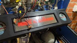
The game deffo boots correctly and I now have the DMD working ok. I can go through the test menu and full attract mode looks correct.
IMG_1170.webp

Lamps matrix is mostly working but noticed quite a few light in pairs… must be a short or something somewhere so will need to look into that.

Switch matrix appears to work correctly by testing a few switches on the pf (not gone through them all yet)

Not having much luck at all with any coils. With all coil wiring plugged in the pops just lock on when game boots. Will try and find there connector and disconnect it so can test flashers and other coils.

I’ll probably continue with the GI work next. The PB connector just needs adding as it was chopped off at some point.
IMG_1171.webp

Then the other end of this connects to the PPB which is also missing… so needs replacing. The only minor issue is I have x3 white - yellow wires!! (Should only be 2 according to schematics) so little confused there. Because it’s just a fuse I assume it does not matter which 1 of a pairs wire goes to which end of the fuse. But not sure what to do about these 3 white - yellows..
IMG_1172.webp

Some wires going to the back box lamp board are also cut so I’ll fix those as well. Basically anything GI has been really hacked up lol.

I noticed my IDC tool I used on WPC connectors don’t seem to work on these DE connectors. Is there a different tool for them? The wire seems to be deeper in the connector.
 
Pretty sure those wires would have looped on the connector. It looks like someone has cut them. So you have two white/yellow, where one has been cut providing you with 3 wires.

I would not be switching on the game with these disconnected like that. As you've found, the coils/solenoids lock on. Once the wires are correctly terminated this might then stop. If the coils have been damaged by being allowed to lock on then they will need replacing and quite possibly the relevant drive transistor. Best measure the resistance of all coils whilst the power is switched off, to see if they need replacing before switching on again.
Ah loop might explain it. Need to figure out which one is the looped though?

These cut wires are all 100% GI so only affecting the 6.3ac GI lamps. Not connected to coils so are ok left alone for now.

With coils plugged in and locking on I turn game off straight away so not damage will have happened.

Iv figured out it’s a few special coils locking on (just the pops, the slings are ok) so not sure if bad transistors or driver chip on CPU.

I can unplug them now so will continue coil tests with them unplugged see if the other ones are ok.
 
You can't react quicker than a fuse, switching a game on and off. Very possible to blow coils, which is why I've warned you.

No need to figure out which is looped, they're all the same (white/yellow). A messy but effective way would be to solder them all together, heat shrink or cap over the solder and connect (push?) ly one of the wires to the connector to make the circuit.
 
Special coils disconnected now, so shouldn’t be an issue for now.

1 of the white- yellow is one side of the fuse and the other 2 will be the other side so can’t just solder them all together as will by pass the fuse. Need to know which 2 are the same wire so can loop it again and attach back to correct pin of the connector.
 
You need to consult the manual and figure out which wire goes where. Use continuity test to confirm you have the correct wires.
 
You need to consult the manual and figure out which wire goes where. Use continuity test to confirm you have the correct wires.
Yeah I know one end is the other cut connector on the pb, just need to figure out the other end now.
 
You need to consult the manual and figure out which wire goes where. Use continuity test to confirm you have the correct wires.
Yup found the one that goes up to the power board. Other 2 must be the loop (ie same wire)

So Iv had another play tonight and found that column 5 (Q67) is locked on, this is causing the multiple lamps issue. Must be a bad column drive transistor on CPU board?

Also found im missing the DC 50v on the PPB the AC is going in ok and the fuse is good but nothing on the 50v DC side so must be a bad rectifier as that’s basically only component between the fuse and the output so will look into replacing that. Hopefully that will be the cause of all 50v coil issues.

Still need to address the locked on special coils, this might be a bad Ic or transistors on the cpu board? If loads of outputs locked on probably bad ic? As not all transistors would go bad together? Also noticed the special coil voltage is 40v dc not the 34v manual says? Is that a little high?

Iv ordered some connectors for the GI connectors so hopefully get some working GI once connectors added back.

Slowly getting there :)
 
Reading the schematic Iv noticed the special coils don’t even connect to the CPU they just have there own switch inputs, wonder if the issue is with those… as when they activated it was only the pops, not the slings!
 
Yup found the one that goes up to the power board. Other 2 must be the loop (ie same wire)
Nice one.

So Iv had another play tonight and found that column 5 (Q67) is locked on, this is causing the multiple lamps issue. Must be a bad column drive transistor on CPU board?
Easy enough to check with a multimeter.

Also found im missing the DC 50v on the PPB the AC is going in ok and the fuse is good but nothing on the 50v DC side so must be a bad rectifier as that’s basically only component between the fuse and the output so will look into replacing that. Hopefully that will be the cause of all 50v coil issues.
Again easy enough to check with a multimeter.

Still need to address the locked on special coils, this might be a bad Ic or transistors on the cpu board? If loads of outputs locked on probably bad ic? As not all transistors would go bad together? Also noticed the special coil voltage is 40v dc not the 34v manual says? Is that a little high?
Perfectly normal as it's probably not being measured under load.

Iv ordered some connectors for the GI connectors so hopefully get some working GI once connectors added back.

Slowly getting there :)
Excellent.
 
Nice one.


Easy enough to check with a multimeter.


Again easy enough to check with a multimeter.


Perfectly normal as it's probably not being measured under load.


Excellent.
Can you test the transistor on the board? Or do they need to be removed first?
 
test on board, use the diode setting on the meter. If in doubt compare with the transistor next to it. It not foolproof but it's a good first test and easy to find shorts when transistors are blown.
 
test on board, use the diode setting on the meter. If in doubt compare with the transistor next to it. It not foolproof but it's a good first test and easy to find shorts when transistors are blown.
Perfect, will give it a go.
 
Only meter test the transistor with the game switched off, I would remove the board and test on the reverse.
 
We have GI!

Replaced the cut off GI connectors and that has fixed the GI issues
IMG_1185.webp

Iv removed the CPU board and have confirmed the locked on lamp column Q67 transistors is bad so will replace that. I also checked all the coil ones and have found x2 bad normal coil transistors and x3 bad special coils (might explain the locked on pops as seems to match those)

I’ll replace all of those as well. Hopefully they are the cause of some of the coil issues I’m having.

On the PPB board the 50v fuse was bad not the bridge rect even though it tested good… (bit weird) But it blew again so issues further down the line.

I got a feeling a few coils might be bad as well from the bad transistors at some point in its life. Is there a way I can test each coil resistance? Ie what is a good reading?

Hopefully get cpu lamps 100% next then just left with the coil issues :)
 

Generally though if the coil sleeve cannot be removed the coil and its sleeve will definitely need replacement.

If you need coils I probably have decent used ones. Just dm me what you need. Black beast branded so as original.
 

Generally though if the coil sleeve cannot be removed the coil and its sleeve will definitely need replacement.

If you need coils I probably have decent used ones. Just dm me what you need. Black beast branded so as original.
Perfect thanks.

Another question, can the CPU board be tested on the bench? ie can I just power it with 5v and it will fully boot and go into attract mode? Or does it need certain switches connected to boot correctly? Would be nice to check all coil outputs are good and not locked on before putting back into the machine. Once bad transistors replaced I guess they just should be anyway?
 
Just realised from reading earlier posts of yours that your cpu boots fine so you don't need Leon's test rom which is useful for non booting cpu.
 
Back
Top Bottom