What's new
Pinball info

Register a free account today to become a member! Once signed in, you'll be able to participate on this site by adding your own topics and posts, as well as connect with other members through your own private inbox!

DE Star Trek 25th (coils locking on at boot)

kev a

Site Supporter
5Years
Joined
Jun 4, 2019
Messages
817
Location
Guernsey
Been contacted by a couple with a DE Star Trek 25 they have had for a number of years but developed a fault a while ago where it stopped launching the ball.
It was clear it wasn't going to be a quick fix so offered if they drop it round I could have a look when I have time and a bit more space to work.

Symptoms were none of the 50v special solenoids or flippers were working at all, the 50v fuse had been pulled and a couple of the coils had been unsoldered and had the wires twisted, presumably by someone previously trying to fault find.
Also has some strange audio distortion that doesn't seem to adjust with the volume pot, and has previously had some battery leakage, although at some point luckily the battery's have been removed before any more damage

Replaced the 50v fuse with the correct rating slow blow, soldered up the coils and powered on, instantly both the kickback and VUK coils locked on and upon testing the matching TIP36 transistors on the Aux PPB board both were shorted.

I disconnected both offending coils to test and everything else seems to be working, ordered and fitted new coils with diodes and replaced the two blown TIP36 transistors, checked the TIP102 transistors on the CPU board and they didn't seem to be shorted. Very quickly powered up/down but the coils locked on and immediately blew the tip36 transistors.

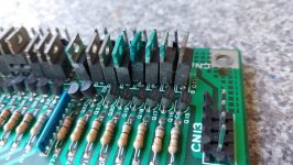
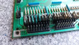
Have replaced the TIP36 transistors again, but this time unplugged CN12 on the CPU board and the TIP36 transistors remained intact without blowing, which leads me to believe its the CPU board holding them on.

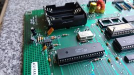
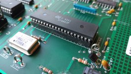
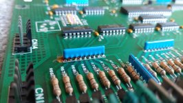
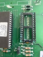
Here's a picture of the CPU board, I plan on cleaning what I can to get a better look, but wanted to document how it arrived. There seems to have been some leakage just below the battery holder, the resistor array has a couple of corroded pins and the tops of the Transistors have got a bit of a splattering too.

20240530_210351_HDR.jpg

A quick question for anyone who has dealt with board repairs with acid damage, is it worth me attempting to replace the TIP102 and pre transistors, or is it a nightmare waiting to happen? I'm conscious its not my game and certainly don't want to cause more damage.
 
Need a close up photo of the area around the battery in order to see how well someone's attempted clean-up was.

You can clearly see corrosion damaged components in the bottom left of the board - must have dripped from the battery directly on to them. Any that are green will need replacing and that connector bottom left. A close-up photo of that area would also help.
Yeah going to pull the board out over the weekend, will get some close up pics :thumbs:
 
Here's some closeups, haven't attempted any sort of clean yet, doesn't look like anyone has

Seems to be most evident directly below the battery holder and the transistors at the bottom, little resistor array looks nasty too 😮
 

Attachments

  • 20240609_155204_HDR.jpg
    20240609_155204_HDR.jpg
    168 KB · Views: 28
  • 20240609_155214.jpg
    20240609_155214.jpg
    141.1 KB · Views: 28
  • 20240609_155234.jpg
    20240609_155234.jpg
    155 KB · Views: 25
  • 20240609_155245.jpg
    20240609_155245.jpg
    159.4 KB · Views: 22
  • 20240609_155347.jpg
    20240609_155347.jpg
    129.3 KB · Views: 28
Last edited:
Board is still being eaten alive as I am writing , needs neutralising and doing exactly what @Moonraker says you are in safe hands as he knows what his is talking about !
 
Very repairable and not much different to this:
Cool! have to admit, I was a bit surprised by the cost of Rottendog replacements, don't suppose its something you would take on? normally I'm all for learning and giving things a go, but apprehensive on someone else's game.
 
I like the mod with the nail in the Rom socket😂

I’m repairing the one in the linked thread above although it’s not data east it’s whitestar

On your board the cpu chip is directly under the batteries so probably it and the socked will be corroded like this was
 

Attachments

  • IMG_3663.jpeg
    IMG_3663.jpeg
    74.2 KB · Views: 16
I like the mod with the nail in the Rom socket😂

I’m repairing the one in the linked thread above although it’s not data east it’s whitestar

On your board the cpu chip is directly under the batteries so probably it and the socked will be corroded like this was
Good point I should really remove the CPU and have a look, the nail.....not my handiwork but I'm remembering that in case I ever snap a leg off a chip 😁
 
I am west of London if that suits and can do this. Don’t have a game to test though.
 
Sadly having to revisit this one, CPU board was repaired and when I got it back played maybe 20 or so full games and left it powered on for hours, to check it was solid, all working flawlessly.

Owners collected yesterday but called to say when they set it up it wasn't working.
Seems to be doing the same thing as before, laser kick and VUK coil locking on as soon as its powered on. the two TIP36's Q1 and Q3 blown along with the 5A fuse at F5
Replaced the fuse, blown Tip36's on the PPB board. powered it on (I think I disconnected CN12 on the CPU) and they blew straight away, instantly.

With CN12 disconnected on the CPU board, the PPB board shouldn't be receiving any voltage to turn on the T36's? but they still blew. Plus that whole CPU section has been rebuilt did a continuity test between the relevant TIP 102s on the CPU to the ground plate at the back, no shorts, so thinking I can rule out the CPU board as the cause, the coils and diodes were also replaced previously too.

Which only really leaves the PPB board, I did go over it previously, but maybe I missed something, could the bridge rectifier be faulty, it seems strange it was working great until it got moved, I checked for any solenoid wires that may have come loose, but didn't see anything obvious, only other that strikes me as strange is the two coils that get stuck share the same colour power wire, coincidence, or does that indicate something?

Gutted I haven't managed to fix it for them, would welcome any suggestions of things to check, as I'm really stumped?
 
Last edited:
Strange it worked your end and is broken again now after transport. Suggests there is something shorting/lose. Would replace the TIPs, disconnect power to the coils and start making my way through the control logic for the affected transistors. If they are on with the CPU disconnected something is broken on the driver board indeed. Shouldn’t be rectifiers or power cable to the coils though.
 
Yeah its really odd, almost like swapping out the CPU board and PPB board broke a short somewhere, and folding the head created it again, If I was to disconnect the coils could I measure voltage between the wires? would I be able to see they are active without blowing the fuse and TIP36's?
 
The coils that are locked on were blown by the original battery damage on the mpu. They needed replacing before putting the repaired mpu back in the game.

You now need to get the repaired mpu back, replace the blown transistors and test it again to check that it hasn't been further damaged by what was locked on. Then visit replacing the blown coils, any ppb transistors and the fuses.

He may then have a working game.
Yeah I replaced the two coils, along with diodes and new TIP36's on the PPB board with brand new before putting the repaired board back in, thats one of the most confusing things, everything up the chain is new now and worked perfectly for many hours until it got moved, I must have missed something, but not sure what.
 
Last edited:
Sorry, he already swapped coils and the pin worked at his end for multiple games including the affected coils. Don’t think this is related to something not being fixed properly in the first place (predrivers may have been marginal) but don’t think this is the issue here. Need to figure out what pulls on the transistors even without coils connected and take it from there.
 
Sorry I should have explained better, I'm now thinking there may have been an existing short or intermittent PPB issue that I didn't spot or overlooked, really hoping something I missed hasn't taken out the shiny new repaired board :(

Really grateful for all the help here chaps, despite being very much a beginner there isn't really anyone else on island who deals with pinballs..... I only went out to look at what I though was a broken ball launch button 😁
 
Last edited:
Just trying to think of a plan of attack for when I visit again, writing it down so I have a checklist to go through, if any of this sounds daft, or I'm missing anything obvious please feel free to point it out, always grateful for advice from those with more experience.

1. Disconnect the two coils, check the resistance is around 4 ohms and fit new diodes on both, leave wires taped up.

2. Replace blown 5a fuse in F5 50v, disconnect the connector from the PPB board and use continuity tester on the mm (one prong on wire going to the coil lug and the other to ground strap) to rule out a short on the playfield wiring.

3. Test the TIP122s on the MPU to see if they have been damaged by using continuity test on MM from the case of the transistors to the ground strap.

4. Either replace the two shorted TIP36's on the PPB and check the diodes on the PPB along with the BR, or perhaps easier if I seek out a used working PPB to rule that out completely.

5. Unplug the connector (CN12) that connects the MPU transistors to the PPB board, power on the game, just want to check how is the best way to see if those transistors are 'on' if they were it should show as continuity between the pin on CN12 and ground right???

6. Plug CN12 back in and measure for voltage on the cables that were unsoldered from the coils.

7, If all that checks out ok plug it all back in and see what happens

Only other thing, seems a long shot but a couple of people on Pinside said they had issues with bad PSU caps causing a low 5v line, in turn screwing with the first part of the CPU boot process, causing coils to lock, I had tested the voltages a while ago and 5v was good, but perhaps its taking a few seconds to ramp up, this game does have an aftermarket LED DMD, so possibly putting a bit more strain on the 5v line, worth replacing those PSU caps too? or any other steps I should add in?
 
Last edited:
On these (as on most pins) ground is switched to the coil by the TIP36C. If you had a short to ground on the playfield wiring the fuse would blow immediately (which is why they did it this way). So no need to measure continuity on the coil cabling. When on, the coils should have 50V present at the power cable. You can just disconnect the switched side and leave power alone.
Now the switched side probably has connectivity to ground if the TIPs are toast - please measure that. If you DON'T have connectivity across the TIPs, they may be fine but always on. Please establish that first.
After a cursory look at the schematics it seems that there are only three coils being driven by TIP36C, knocker, ramp down and Turbo Boost kicker. Does the knocker work? These work by pulling the TIP input low, meaning you should have a voltage at the TIP base at rest. This is supplied by the coil voltage via controlled cable and pull up resistor R15/16/16 (yes, two times 16 according to schematics, probably R17), so you will only have that when the coil is fully connected!
Interestingly, the pre drivers are on the CPU board, Q39, 40 and 41 respectively. These drive lamps in parallel, coming from PPB J9-10 BLK-BLU, -11 BLK-VIO, -12 BLK GRY. These lights are in the ramp 1x and playfield 2x. Please identify those lights, their power supply is via an orange cable. If these lamps work the TIPs are shot for sure.
So plan of action:
  1. Pinball OFF
    1. Disconnect switched cable from coils
    2. Identify lamps
    3. Measure resistance collector - emitter on TIPs - short?
    4. Measure coil resistance - good?
    5. Measure pull up resistors - 220 Ohm, continuity to PDB J8-10 and -2 and D17/18 respectively?
  2. Pinball ON
    1. Are the lamps working?
    2. Do you have power at the coils?
    3. Is the knocker working?
If we have yes on 1.3., 1.4., 1.5., 2.1., 2.2. and 3.2. the TIPs are gone and need to be replaced, pin should work afterwards.
Now for the TIPs burning up in the first place:
- If the lamps don't light/are always on the pre drivers on the CPU are shot, measure and fix
- If the TIPs don't have a positive bias on their base at rest they may turn on and consequently burn up - this would be caused by the 220 Ohms resistors being defect - this may be caused by cold solder joints, please check for this as this could be the transport issue and reflow if needed

Any questions, ask :)...
 
Brilliant thank you, I did download this tech chart, seems there is a couple more things running from TIP36's on the PPB board.

1728906570410.webp
Thinking back to when I first looked at the game, when the issue happened the first time, with 14 and 15 disconnected 3L and 6L definitely worked as expected, knocker im not sure about.

When I left the game yesterday, both Q3 and Q5 were shorted for sure, wondering if it would be easier to get the game back here where I have more room and go through your steps one by one and post the results.
 
I went from the schematics on ipdb.org - wouldn't be the first time they aren't really game specific and therefore wrong. But the steps are still directionally right - if the lamps on the same CPU drive work it must be the TIPs. The only other thing being able to switch them on would be the pull up resistor. This is also a good test for the 5V theory, if the drive is stuck on, coil and lamps must be on together.
 
Ok Cool, just so I understand, I think so but its a bit of a learning curve.... the drives on the CPU, control both the coils and those flash lamps, so if the lamps work as expected (not stuck on, or stuck off) that rules out transistors on the CPU board and we have narrowed it down to the PPB, possibly those pull up resistors?
 
Yes, the transistor on the CPU board drives both the coil via the TIP36 and the associated lamps directly. If the coil is stuck on while the lamp works it either is the TIP or something pulling the base of the TIP low therefore. Latter could be a short of some sort (a screw rattling around behind the board e.g.) or the pull up resistor. Not much else qualifies
 
Back
Top Bottom