What's new
Pinball info

Register a free account today to become a member! Once signed in, you'll be able to participate on this site by adding your own topics and posts, as well as connect with other members through your own private inbox!

Coils won't fire (X-Files)

Spanky

Registered
5Years
Joined
Sep 6, 2015
Messages
75
Location
Glasgow
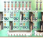
Symptom: when you turn it on, it goes CLUNK CLUNK CLUNK and the filing cabinet goes down and up. You can start the game, but no ball appears.
The coil tests seem to do nothing. Flippers work. I've checked DC voltages coming out of all the bridge rectifiers. What's next, the power transistors perhaps or U1 & U2?

Thanks in advance.
 
All fuses are visibly okay, the four red LEDs on the power board are all on.
 
Well what do you know? F21 had blown.
I swapped F20 and F21, but the problem persists.
 
Last edited:
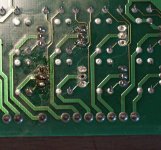
scrape off that crud. ipa and a gentle scrape. check nothing shorted.

test all fuses and put new ones in. power on see what happens. if not working then power off and check all fuses again. any blown? if so something shorted. if not then problem probably further up the board.
 
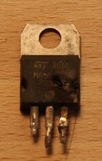
Check the manual, some transistors may not be in use for this particular game.

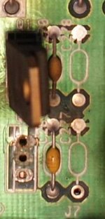
That top Q2 leg on the last pic definitely looks like it could use some more solder!
 
Check the manual, some transistors may not be in use for this particular game.

That top Q2 leg on the last pic definitely looks like it could use some more solder!
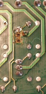
Yup, someone has had a hack at Q2 and Q3 and those missing two don't look like they were missing out of the factory....perhaps swapped as replacements for Q2 and Q3 in the past if not needed.

As above, remove old solder, clean up, take a breath and do a nice job on putting replacements in. :)

If it doesn't fix it, you won't need to come back to this bit again ;)
 
Correct. I've got one, just need to work out an elegant way of fitting it, since the PCB tracks are buggered.
 
I'm thinking I'll just solder some longish wires onto the replacement MOSFET and mount it nearby. That's all I can do as the tracks are buggered. Shouldn't look too sloppy.
 
I'm thinking I'll just solder some longish wires onto the replacement MOSFET and mount it nearby. That's all I can do as the tracks are buggered. Shouldn't look too sloppy.
Don't do that - it's manky, will look crap and will scare off any future repair person!

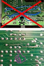
Clean the old solder from the dodgy tracks with solder wick. Then scrub the old flux from the board (both sides) with an old toothbrush and acetone or similar (steal the wife's nail polish remover). Then fit new parts as neatly as possible IN THE CORRECT HOLES. After that, use a piece of single strand bell wire to make the connections from the new parts to the closest available pad position possible.

repair2.jpg
 
Well I'm open to suggestion, but this is what I've got to work with:

DSC06184-small.jpg
P.S. Wasn't me who buggered those tracks
 
Ok so the top one seems to be in tact still (needs metering out).. The middle one you could bend that leg out to the Track adjacent.. Doesnt look like there's anything connected to that one.... Any chance of a flip pic of the same spot?

Needs a clean up, however from an initial view of the above, deffo doable so far..
 
DSC06187.JPG

At this point, some may be wondering whether I'm a traffic warden by trade who barely knows which end of a soldering iron is which. For the avoidance of doubt, I did study electronics for a year in tech college back in the day, and my first job was soldering boards.
 
Last edited:
I bought a through hole rivet kit for such jobs, and a sheet of adhesive copper to make new tracks for wpc89 that went on fire! Not got round to it yet, with a bit of time you could make that look the part
 
That's very easy to fix the way I suggested above and you will end up with a board that looks 'repaired' not butchered!
100% agreed with the above, but I would expand on that advice as I really dislike protruding bare tracks on boards - once the new wire is formed and in place, put some UV soldermask on there, and you have as perfect as you can hope to do with basic materials.
 
I'll try remember to take more photos of this Whitestar I'm repairing as I go along, and post them up here in sympathy. The acid damage on it is unreal - somewhere in the region of about 30 unique track breaks (and of course some of those 'breaks' are more like 'track entirely missing' as is the nature of severe acid damage...)

We're not dealing with high-frequency equipment here - for our purposes, all a PCB is, is a bunch of very flat copper wires holding a bunch of parts in a fixed formation. Just get those electrical pixies from point A to B in a tidy way and you're golden.
 
100% agreed with the above, but I would expand on that advice as I really dislike protruding bare tracks on boards - once the new wire is formed and in place, put some UV soldermask on there, and you have as perfect as you can hope to do with basic materials.
UV soldermask, never come across that before, sounds intriguing....Google here we come...
 
UV soldermask, never come across that before, sounds intriguing....Google here we come...
There's a mild learning curve to applying it and curing it properly on a home-etched board so it's uniformly flat, and doesn't cure over your solder pads so you can just wash that off leaving your printed soldermask on the board - but in this particular use case, it's actually a brilliantly easy-to-use sealant, or even as a glue, of sorts.

I've used it to lay down flat bits of copper to replace missing/destroyed pads for surface-mount chips (nightmare, finicky crap to have to do.) Of course, without fixing those new 'pads' in place, they'll just fly away once the hot-air gun comes out... but not if you paint over the track part with soldermask and cure it first. That bugger will be going nowhere. UV soldermask cures almost as hard as the soldermask already on the board, and just as heat-resistant.

Awesome thing to have lying around for repairs of this sort. Just try and match the colour of the board though because it looks like utter crap if you use the wrong colour!
Thanks @PBrookfield looks awesome. I'll try some :)
 
Back
Top Bottom