jacksonsinliss
Registered
Does anyone know how Coils are described by their Product Codes? The Williams codes appear to be two pairs pair of numbers, such as FL 20-300 / 28-400 for the Flippers (FL?) so it may be that this is the AWG and the number of turns. The first pair is the primary/Kick and the second pair is the secondary/Hold?
I have two Williams Flipper Coils from a 1958 machine (Kick Off) that have wires of different gauges: they both have no wrappers so no ID, the right flipper coil has a primary coil that is 22 AWG and the left flipper coil has 18 AWG wire. Obviously, at least one has been replaced, probably the one that has the thicker wire - it also has the designation "SMIRG 6B"? I think the correct coils might be either FL-21-375/28-400, like 1964/5 machines, or they could be FL 25-930/31-600, like the 1959/60 machines, but if anyone knows for sure then please let me know. I cannot find a Schematic for this machine so I can only go on the machines closest to it in age?
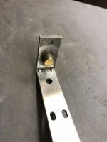
FYI, I am refurbishing this machine and it has been messed with so this is just one mystery to solve. How the cabinet came to have had metal rails fitted is for another post when I get around to that!
I have two Williams Flipper Coils from a 1958 machine (Kick Off) that have wires of different gauges: they both have no wrappers so no ID, the right flipper coil has a primary coil that is 22 AWG and the left flipper coil has 18 AWG wire. Obviously, at least one has been replaced, probably the one that has the thicker wire - it also has the designation "SMIRG 6B"? I think the correct coils might be either FL-21-375/28-400, like 1964/5 machines, or they could be FL 25-930/31-600, like the 1959/60 machines, but if anyone knows for sure then please let me know. I cannot find a Schematic for this machine so I can only go on the machines closest to it in age?
FYI, I am refurbishing this machine and it has been messed with so this is just one mystery to solve. How the cabinet came to have had metal rails fitted is for another post when I get around to that!