What's new
Pinball info

Register a free account today to become a member! Once signed in, you'll be able to participate on this site by adding your own topics and posts, as well as connect with other members through your own private inbox!

Building a Topper

Judderman

Site Supporter
5Years
Joined
Mar 28, 2016
Messages
1,070
Location
Cheshire
I've been thinking of making an alternative topper for my LW3 & bought these, hoping to take the power from a 12V feed https://www.amazon.co.uk/gp/product/B0183BJCM4 - looks fine, but when powered on, you need to press one of the buttons to select a pattern. I tried turning them on with one of the buttons pressed down, but that didn't work (didn't really expect it to TBH).

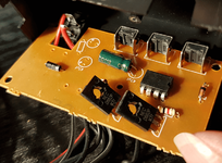
I took it apart & this is the circuit
1648759743448.png

Looks fairly simple, but I have a couple of questions - is there an easy hack to simulate an immediate press of one of the buttons (the 3 things along the top) when power is applied? If not, it looks like I actually have a job for that arduino kit that's been sitting in the drawer for a couple of years.

Is there anything on there that would change the voltage output to the LEDs from the 12V in?
 
Flashy!

I can't see any power regulation on that board - seems everything is 12v (which is the input voltage) from what I can see.

What happens if you keep the button pressed?

It looks like a couple of Tips to manage 2 switch cycles and a micro processor to manage the tips with different preset cycles.

Would you want this light flashing all the time? Could get a bit annoying.

Maybe checkout @stumblor new pinpoint board and do something far more interesting based on certain events?
 
Maybe checkout @stumblor new pinpoint board and do something far more interesting based on certain events?

Thanks mate but Pinpoint currently has no support for DE. It should be easily to implement, just a different pin arrangement, but haven't looked into it yet.

What happens if you keep the button pressed?

That was my thought too I'm surprised that this didn't initiate the flashing on power up. It would be fairly easy to do something yourself using the Arduino (ditch the board entirely but keep everything else), using one of those little mosfet boards that @AlanJ uses, similar to this:


Pretty sure you could drive those using PWM also, which could mean you could add some fading effects which would make the flashing less harsh.

Arduino Nanos can take 12V so you could keep voltage the same as it is now.
 
Cheers both - realised while I was cleaning my teeth that I could just have checked the voltage with a multimeter.

Only want it active when the blue flasher is currently active, but it's a bit flaky on the rotation 'cos of the worn rubber ring - that's what gave me the idea to replace it.

Will prob go down the Arduino route just out of interest, should be fun (& good practice for the Star Trek topper I'm thinking about, too, for which Pinpoint is also unsuitable)

Stew
 
Back
Top Bottom