What's new
Pinball info

Register a free account today to become a member! Once signed in, you'll be able to participate on this site by adding your own topics and posts, as well as connect with other members through your own private inbox!

BSD ground short issues HELP!!!

newdos

Site Supporter
10 Years
Joined
Jan 14, 2013
Messages
3,162
Location
Hartlepool
OK so my BSD suddenly developed a ground short issue on row 2 as shown below. First Thing I did was test the CPU by jumpering J207 to J209 pin by pin, and all was good. All 64 switches working fine, so NO CPU issue.

I also checked from the j209 pin 2 to ground to see if there was a direct short and weirdly there wasnt according to my meter (see opto board bit later)

IMG_6859.JPG

So I started to trace the wire from the J209 pin 2 into the machine to try and find the first switch. I thought it was the trough switch 2 which is switch 42 so I disconnected this wire to test for continuity back to J209 clearly it was this one as there was no reading on meter. so put wire back on and switched machine on and suddenly now we have 3 ground short rows at fault WTF!!! as below
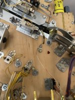
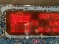
IMG_6865.JPG

IMG_6864.JPG

So after this I had heard of issues with the 10way opto board so unplugged J3 from it which has power to the board (LED is on the board) and the J209 switch wires. Instantly now I have no ground short faults at all see below. Does this explain why there wasnt an actual ground short on the original row 2 when I metered it out earlier ???

IMG_6858.JPG

So is this a case of opto board had gone bad and then suddenly developed more faults ???? I did notice this board is quite warm - is that normal. If it is this board is it likely to be the 3 x LM339 on board which I could replace before forking out for a new board.

All help appreciated. TIA

Cheers

Kev
 
I think you have worked out what I saw and fixed on mine. The schematics shoudl show you which of the LM (s) needs replacing, to fix that short.
Yeah also notes that rows 1-3 are all on 1 IC ie U1 which makes life easier. dOES ANYONE KNOW IF THESE CHIPS CAN BE TESTED ON BOARD IN ANYWAY TO PROVE IT FIRST ?

Cheers

kev
 
You can, with a logic probe or an osciliscope. But honestly, you have done a lot to show it is most likely this chip on that board, and I had the same.
Are you happy to swap the chip?
 
You can, with a logic probe or an osciliscope. But honestly, you have done a lot to show it is most likely this chip on that board, and I had the same.
Are you happy to swap the chip?
Yeah sure am will order some up and go for it. Cheers bud
 
While you're working the opto board, check that the capacitor (C1) hasn't leaked.... that can also cause issues. It might just be best to swap it out anyway.
 
You can, with a logic probe or an osciliscope. But honestly, you have done a lot to show it is most likely this chip on that board, and I had the same.
Are you happy to swap the chip?
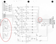
Well I have replaced C1 and removed U1 from the board and put a socket in ready for the chip arriving. I refitted the board and expected the 3 rows of ground shorts to disappear with U1 missing but weirdly they still show. However I note from the schematic (below) that rows 1, 2 and 3 and shared with optos on j4 j5 and j6 on the board so I guess that could be showing weird results with stuff floating?

Will update once the new Lm339 is in

Cheers

kev

1722074544909.png
 
So the plot thickens!! replaced U1 LM339 and still 3 ground row shorts on rows 1, 2 and 3 - anyone any other ideas ????

TIA
 
I feel i directed you to the board but it is worth backing up and checking where we are on the basics:

  1. If you disconnect J209 on CPU, does the short dissappear
    1. If No, the issue is on CPU board,
    2. Try J208, does short still exist
  2. Is there are an issue with the connector to J209, are white-brown(J209-1), white-red(J209-2) and white-orange (j209-3) all ok and not bridging?
    1. Check continuity between these wires (game can be off)
  3. Now check the connector at J3 at 10 opto connector
    1. Disconnect, does issue go away? If yes, the board is the issue
      1. j3-12 (row1), J3-11 (row2), J3-10 (row3)
      2. Check continuity between these wire (game can be off)
      3. J3-1 is ground to PDB, J3-2 is 12V, worth checking this is here

If not the CPU and not the 10 opto, then we look elsewhere
Thanks for the help bud see answers below

1 yes
2 yes
connector looks fine same result on j208 and j209
yes if i remove j3 on opto board it goes away (all described in the thread above!)
continutiy good back to j209 from j3 on opto and 12v and gnd all good

Cheers

Kev
 
So i did about my checking. if I remove each plug one by one from CPU it makes no difference until only j209 is left and removing that removes all the ground shorts.

So because J4, J5 and J6 are linked to rows 123 I removed each of these connectors - only one that did anything was J6 which is linked to row 1 and it cleared that fault, but rows 2 and 3 still showing as grounded.

Removing J3 from the opto board on its own clear all the faults. From this I'm wondering if also replacing U3 maybe the next job to see if there is an issue with that ?

Thoughts anyone ?
 
Lets try and fix one issue at a time, see what we can isolate and then see if they are connected.

These are those issues that are like a really good puzzle, and you need to be in the zone and have the time to unpick.

J6 is U3C (row 1)

U3A is row 3
U3B is row 2
U3D feed the input for U3C

My advice would be to socket and change U3
Thats what I was thinking bud! will be end of week before I get it done as off to 100 cricket today!
 
Lets try and fix one issue at a time, see what we can isolate and then see if they are connected.

These are those issues that are like a really good puzzle, and you need to be in the zone and have the time to unpick.

J6 is U3C (row 1)

U3A is row 3
U3B is row 2
U3D feed the input for U3C

My advice would be to socket and change U3
Ok so I changed U3 and that has got rid of the ground row shorts on rows 1 and 3 - so right back where I started!!

SO, next I thought it must be something to with J5 as that is also connected to row 2. As soon as I remove J5 row 2 ground short vanishes!! jackpot I thought, something must be wrong with the opto set on the coffin popper. next I disconnected the opto and yes error goes away, so I then replaced both transmitter and receiver LEDs with new ones. I tested the opto set (as I had removed it from the coffin popper) and connected it to the opto that is on J6 and it works fine, so I now know the opto is good.

Here is the wrap though!!! as soon as I connect the new opto back to J5 ground short appears aaarrrgh!!!!!! I have even removed the key pin from J5 so I can plug it on J6 (or J4) to test the wiring loom and of course with the new opto and the original loom now connected to J6 on the board it works fine, so this now proves it is something on the board that is pulling down J5

Cant see what else it can be that can be changed on the board? HELP!!! @Calimori

TIA

Kev
 
Last edited:
I'd test all resistors are working and one isnt open circuit , specifically R26 and R10 and also test/replace D11 & D2. Also check the resistors are wired up the the other components (i.e. have you got a broken trace somewhere).

If that doesnt help then You already replaced U1, but could try swapping U1 and U2 if they're all socketted?
 
@myPinballs Jim you wouldnt have any ideas on this mate ?

Cheers

Kev

Change D11. You cannot trust a diode tested in circuit

Also, my plan of attack with a board like this would be to bench test it with a logic probe and manually activate each comparator to check they work as expected.
 
Last edited:
Sorry @newdos for missing this, I actually hunted it down today to see how you got on, no idea how I missed the notification.

I spent a lot of time on Friday getting reacquainted with this board on one I had that didn't work. @myPinballs has the knowledge and experience to test a theory, I am only able to work through components that could be an issue and then check them.

The key thing I learnt on friday from working through the schematics, is that J4, J5, J6 all do the same thing for the short beam optos

J(4,5,6) Pin 1 is the 12V for the LED Board - J1-9 is the common negative
J(4,5,6) Pin 5 is the negative - J2-9 is the shared 12V for the receiver or Photo Transitor - Here the Pin 5 goes through U3 but the power needed for the IC also goes through U3.

If J5 is causing the negative earth, I would then check if that was from J5-5 being removed to isolate it in the circuit through U3B. First, I would disconnect the Orange-Black wire from the Opto reciever for the coffin popper as I can quickly re-solder that if no change.
Assuming that causes the fault to go, I would then investigate the following highlighted routes for the negative to short, off which there is only four components.

As you said, they all test but I would then check D11 visually and change it anyway because LN4004 seem to test fine but under load act funny.

Screenshot 2024-08-06 at 10.32.09.png
 
Change D11. You cannot trust a diode tested in circuit

Also, my plan of attack with a board like this would be to bench test it with a logic probe and manually activate each comparator to check they work as expected
Cheers Jim will give that try - watch this space!
 
Just out of curiosity, there are wires running to J212 on the CPU board (cabinet switches). In your text, I didn't see any mention of testing done in this area. Given that J212 also connects in parallel to columns 1, 2 and 3 - and also rows 1, 2, 3 and 4 it might be worth looking at.

For example, if one of the switches connected to J212 pin 6 (row 2) had a problem, it could manifest itself as a problem with all switches on that row. I believe this connector goes to the coin door board. According to the manual, J212 pin 6 connects to J1 pin 5 on the coin door board - which in turn connects to the front door switch via a diode.

Please can you confirm you've tested this bit and eliminated it as a possible cause?
Yeah I have done that but not mentioned it as when J5 is removed from the 10ch opto board the gnd short vanishes so really points at that board. if i remove j212 from cpu no change other than coin door closed switch goes off

Cheers

Kev
 
Sorry @newdos for missing this, I actually hunted it down today to see how you got on, no idea how I missed the notification.

I spent a lot of time on Friday getting reacquainted with this board on one I had that didn't work. @myPinballs has the knowledge and experience to test a theory, I am only able to work through components that could be an issue and then check them.

The key thing I learnt on friday from working through the schematics, is that J4, J5, J6 all do the same thing for the short beam optos

J(4,5,6) Pin 1 is the 12V for the LED Board - J1-9 is the common negative
J(4,5,6) Pin 5 is the negative - J2-9 is the shared 12V for the receiver or Photo Transitor - Here the Pin 5 goes through U3 but the power needed for the IC also goes through U3.

If J5 is causing the negative earth, I would then check if that was from J5-5 being removed to isolate it in the circuit through U3B. First, I would disconnect the Orange-Black wire from the Opto reciever for the coffin popper as I can quickly re-solder that if no change.
Assuming that causes the fault to go, I would then investigate the following highlighted routes for the negative to short, off which there is only four components.

As you said, they all test but I would then check D11 visually and change it anyway because LN4004 seem to test fine but under load act funny.

View attachment 257968
OK so what I have done to rove loom is ok i disconnected the opto from the coffin popper and the error goes away. is that what you mean?
D11 replaced no and no change.

Just checked R27 2k spot on and R26(diagram says R6 which is wrong!) and it appears to be open circuit!!! yet not a mark on it very odd. I will change it and come back

Cheers

Kev
 
Thanks for that - just a thought ;) .

Do you have another machine you could test the 10 ch opto board in? If not, I'd be happy to test and repair the board for you (I can get references from members on this site if it helps).
 
Back
Top Bottom