What's new
Pinball info

Register a free account today to become a member! Once signed in, you'll be able to participate on this site by adding your own topics and posts, as well as connect with other members through your own private inbox!

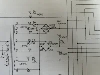
Bally Rectifier board voltage issue on 230VDC at TP2 ( Harlem Globetrotters on Tour )

kamalackarie

Site Supporter
Joined
Jun 1, 2023
Messages
48
Location
London
HI all
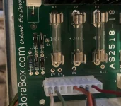
I recently got a HG on Tour at auction - the rectifier had been hacked - I swapped it out for a new one from pindorabox.
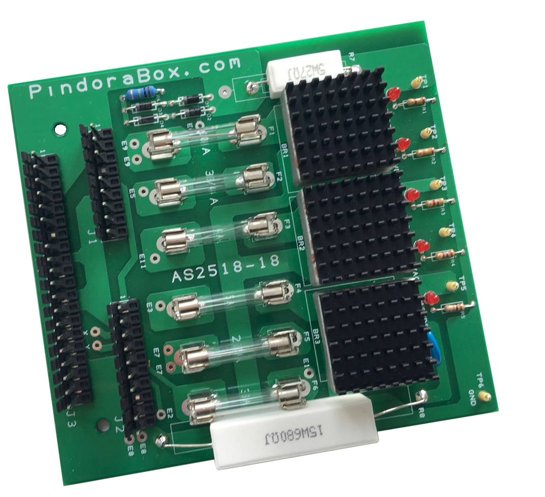
all my AC readings off the transformer are good. J1 and J3 are disconnected
readings on TP1/3/4/5 are as they should be

I have a problem with TP2
I should be getting 230VDC at TP2. Instead I am getting 31VDC.
I checked the Voltage across E5 and E6 thats good at 178VAC
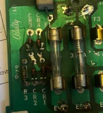
CR1 - CR4 all test good at 0.584
R3 tests at 150 ohms - should be 100 ohms- I have not isolated it from the board so cant be certain this reading is not affected from it being in circuit.

what am i missing here / doing wrong??

The 230VDC powers the displays.

so guess whilst i am working this out i can connect J1 and J3 and see if i can get he MPU to boot
 

Attachments

  • IMG_3672.webp
    IMG_3672.webp
    91.9 KB · Views: 14
R3 should be 100,000 ohms ?? 100k

But anyway test the voltage pre r3

Also check the negative side of the 4 diode bridge rectifier is connected to ground
 
My suggestion would be to work it through.. Check the voltage out of the Txfmr.. then the fuse at F2.. left to right... etc etc
Not sure if the diodes will test ok in circuit (note they are set as a bridge) - gotta be worth a try though... you may have to lift a leg on each to get a decent reading...
 
R3 should be 100,000 ohms ?? 100k

But anyway test the voltage pre r3

Also check the negative side of the 4 diode bridge rectifier is connected to ground
sorry yes r3 tests as 98.7 Kilo Ohms - so within tolerance
when i test voltage pre R3 i get 241 VDC on the other side I get 41 VDC
 
Fairly new to this - in regard to testing that the negative side of the BR goes to earth.
The Anode end of DR1 and DR2 go to earth ( continuity ) on the original Bally board these are marked as CR3 and CR4 - for referencing the schematic - to my eye this is correct.
 

Attachments

  • IMG_3681.webp
    IMG_3681.webp
    116.7 KB · Views: 18
  • IMG_3682.webp
    IMG_3682.webp
    109.7 KB · Views: 17
You may have a faulty or poor voltmeter. If the voltmeter is drawing too much current, you will get a voltage drop across the resistor. Usually a voltmeter draws hardly any current so the voltage drop is negligible.

Voltage drop = current (A) x resistance (ohms)

You are measuring a voltage drop of around 200v which implies a current of around 0.002 or 2mA for a 100k resistor.
 
on further investigation
When I test TP2 (230VDC) I get a reading of 46VDC as mentioned previously
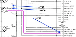
When I measure across R3 I get 239VDC at one end and then 46VDC at the other. But as its been mentioned this only serves TP2 so maybe a red herring

Following the path to Pin 5 of J3 I get a reading of 159VDC which to me doesn't make sense as i have 239 at R3 and there is nothing in the path between Cr1-4 and pin 5

all of the above is part of me trying to get the displays working - which all measure 0vdc at their High Voltage Test points.
 

Attachments

  • Screenshot 2024-12-18 at 13.43.37.webp
    Screenshot 2024-12-18 at 13.43.37.webp
    56 KB · Views: 4
actually the readings i gave were with J3 plugged in
I have unplugged J3 and now i get lower readings
TP2: 37VDC
R3: 157VDC in - 37VDC out
 
Replace those bridge diodes
Thanks Alan. I had suspected this to be the case. Its a new board - so has arrived fauty if this is the case. i will replace the diodes - eaiser then returning the board. I will keep you updated and hopefully be back with a positive result.
 
update
all diodes tested ok
i wrote to the manufacturers of the board about this issue and got this back..
The testpoint for the 240v can be ignored, in the new version this will be changed to another circuit. The led was just added to make it visible, the testpoint is not the correct circuit placement.
seriously !!!!
this led me to do some more investigating around the 230VDC that i needed that i can dial back to 190VDC, Transpires this is rectified on the Solenoid Board. i tested at TP2 on the solenoid Board and there it is 240VDC
the HV adjust was at full so i dialed it back to 190VDC as it needs to be on the schematic. then tested the 3/16Amp fuse ( which i swaped out for new on weekend - previous owner had hacked this). and it was dead. Fortunately i had a spare and on power up i have 4 displays "kind of working" and one dead.
so my next task is to find out whats up with theses displays - any help appreciated

oh is it possible to repair a dead display - assuming its a bad component?
 

Attachments

Back
Top Bottom