Hello,
Could you clarify how you mean, End of Stroke switches being tested?
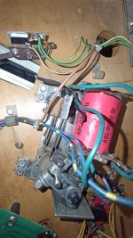
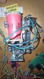
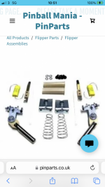
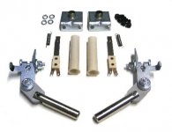
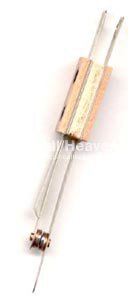
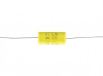
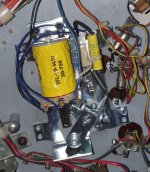
1992 is a bit later than Bad Cats, which is firmly in the era of parallel-wound 'conventional' flipper units, with solid-state 'Lane Change'/Status Report/Initial Entry. As such, each flipper has a tungsten-contact switch fitted, which is normally closed. The arm on the flipper linkage pushes open the switch to shut off the primary winding of the coil. A capacitor connected across the EoS switch (and cable-tied to the upright), absorbs most of any back-emf voltage, which otherwise will burn the switch contacts. It looks as if that's what's happened already, and a couple of switches lying about have been fitted. For the right side, what's fitted isn't anything like the proper part, maybe it's for an old Bally type. The 2nd part of that switch, with a diode attached, is totally unnecessary; it may have been used for a Lane Change switch on some earlier installation, but not here. The switches in that 1992 kit couldn't cope with the current involved here; they're used to show a Fliptronic circuit board (and cpu/game program) that a flipper is raised.
As to diagnostics, a 'pre-Fliptronic' game like this doesn't have a 'Flipper Test' section. The flipper relay switches On when going into Bookkeeping/Diagnostic, and that's it; pressing the buttons should operate the flippers. The only time anything concerned with the flippers will show on the displays is in the Switch Tests, i.e. Levels, or Edges; the name 'Left Flipper' or 'Right Flipper' appears with its number when the flipper is operated (electrically, not by moving the flipper manually).
There are not power transistors controlling each flipper coil winding for this game; pressing a flipper button allows current to flow through both the windings of that coil, the closed EoS switch, the button contacts and the relay. The switch opens when the flipper is raised, cutting out the high-power winding of the coil, which would otherwise burn out in a few seconds if the flipper was held raised. A safer low current continues to flow through the Hold winding of the coil and keep the flipper raised, if necessary. As I understand it, 'voltage switching' is a data east method, so a single-winding coil can be used.
The Lane Change feature of later System 11 games uses a couple of tiny opto-coupler chips to sense flipper current, and link to the switch matrix. They're placed on the Backbox Interconnect circuit board, below the Cpu/Driver board. This keeps the switch matrix wires away from the 50v power wires at the flippers themselves.
