Hi all,
Looking for a bit of help. The issue is, various switches inside the cabinet are not triggering - Ball Launch, Left Handle Button, Start button and Plumb Bob Tilt.

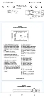
So from looking in the manual it appears my issue is with the green-brown cable. I've checked the green and brown cable with my muiltimeter and I appear to be getting a reading from all the above mentioned switches (11, 12, 13, 14 in above pic) The issue only appears to affect the green-brown cable in the cabinet switches as when i test the green brown cable on the playfield switches for Left Outlane/Inlane etc then these switches work fine (15, 16, 17 in above pic).
Some background to this:
Paul has very kindly helped me get this far, but I dont want to keep bugging him so decided to write this post and ask the rest of you for suggestions. I've tested the cpu board by jumping from the connectors - eg Ball Launch - placed jumper wire from J207-1 to J209-1 and it triggered the ball launch on the matrix tests.
The CPU board is also a new Pinsound one that I purchased a few months ago. The power driver board has been away getting repaired over the past few months too. When I bought this machine, it was a project - batteries had leaked so I had no idea what worked and what didn't. After I put the new CPU board in the Start and Ball Launch buttons kind of worked - you had to press them a couple of times before they registered, so something was iffy. I then noticed the game was having power issues and resetting for no reason - could be sitting in attract mode and it would bounce. Hence why I sent the power board away.
Like I said, multimeter shows voltage through all of the cables going to the affected switches. Wires all appear to be connected properly (as far as i can see). So my troubleshooting continues and i'm looking for options as to what i can try next. Should add i'm already out my depth here and needed help to get this far so i'm hoping for any other simple things to try first as anything major is probably gonna be outwith my skills.
Thanks,
Jason.
Looking for a bit of help. The issue is, various switches inside the cabinet are not triggering - Ball Launch, Left Handle Button, Start button and Plumb Bob Tilt.
So from looking in the manual it appears my issue is with the green-brown cable. I've checked the green and brown cable with my muiltimeter and I appear to be getting a reading from all the above mentioned switches (11, 12, 13, 14 in above pic) The issue only appears to affect the green-brown cable in the cabinet switches as when i test the green brown cable on the playfield switches for Left Outlane/Inlane etc then these switches work fine (15, 16, 17 in above pic).
Some background to this:
Paul has very kindly helped me get this far, but I dont want to keep bugging him so decided to write this post and ask the rest of you for suggestions. I've tested the cpu board by jumping from the connectors - eg Ball Launch - placed jumper wire from J207-1 to J209-1 and it triggered the ball launch on the matrix tests.
The CPU board is also a new Pinsound one that I purchased a few months ago. The power driver board has been away getting repaired over the past few months too. When I bought this machine, it was a project - batteries had leaked so I had no idea what worked and what didn't. After I put the new CPU board in the Start and Ball Launch buttons kind of worked - you had to press them a couple of times before they registered, so something was iffy. I then noticed the game was having power issues and resetting for no reason - could be sitting in attract mode and it would bounce. Hence why I sent the power board away.
Like I said, multimeter shows voltage through all of the cables going to the affected switches. Wires all appear to be connected properly (as far as i can see). So my troubleshooting continues and i'm looking for options as to what i can try next. Should add i'm already out my depth here and needed help to get this far so i'm hoping for any other simple things to try first as anything major is probably gonna be outwith my skills.
Thanks,
Jason.
Last edited: