What's new
Pinball info

Register a free account today to become a member! Once signed in, you'll be able to participate on this site by adding your own topics and posts, as well as connect with other members through your own private inbox!

Noob Switch Fault Tracing

Wiredworm

Registered
10 Years
Joined
Apr 7, 2013
Messages
2,373
Location
Grimsby
I've had my R&B stripped for cleaning and then rebuilt it. I thought it had gone without hitch but I've noticed that I rarely if ever get the option to choose an award along with the 'I can't make up my mind' audio cue.

Anyway, tonight it's got the better of me so I've lifted the Playfield, gone I to the switch test menu and sure enough the switch in the subway that leads down to Aesops Hole isn't registering. Cabling looks ok but there's heat shrink over the cable to the middle pin so it's possibly a poor connection there.

Can someone please provide me with an idiots guide on how to proceed from here? I have a multimeter I can use if needed but what's the best step to take next? The switch has a definite click when registered so I don't think the switch has failed.

Thanks

Pete
 
Aaaaand it gets better. Whilst I had the menu on I noticed I've not just lost switch 37 (under trough) but ive lost an entire column of switches.

I've lost column 4 which is switches 33 through 40. I've removed connectors 8 and 10 from the CPU board and entering test mode shows no issue so based on what I've read that points away from a CPU board issue.

:(

Amy clues on this one and how to go about fixing it please?
 
Last edited:
Would a break in either wire (drive or return) at any point in the chain cause all switches to fail? Or just the ones after the break?

In case you'd not guessed I'm totally new to this. :)

My guess is that as the switches are connected in series I should be able to measure continuity on either of the wires between two switches in the chain. So if I get no continuity between 33 and 34 then I know that's where the break is. I can therefore work my way along the chain until I get no reading and that should give me a clue where the problem is?
 
Last edited:
The drive wires on this table have all got a kind of rubber boot on them so it makes it a little tough to see if one has managed to come loose.

I've had a look under the playfield and from the manual I can see the affected switches all share the same drive cable which is green with black. One of the switches only has single green/black wire going to the center post so I assume that's the last in the series.

I unhooked that and put my negative probe on the meter into it. Based on the documentation the first switch in the column is the gate at the entry to the left loop. Sure enough when I put the positive probe onto the center post I get no continuity but here is where it get's weird.

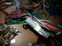
The switch of the left loop entry isn't wired in directly. The cables from it go to a pin header and the other side to which that connects has the drive and returns looped through it. To my mind this means that even if the switch was mis-wired or disconnected then the drive should still continue onto the next switch? Or maybe i'm misunderstanding?

20130904_212240.jpg

I also disconnected the center post on the switch at the left loop exit and tested continuity from there and got a beep. Also got a beep when connecting my probe to the green/black cable shown above on the receptacle into which the pin header connects.

Really strange :|

Just so i'm clear though. If the issue was the return then it wouldn't be affecting all switches in the column. In that case you'd get failure of all switches on the row?

So in this case i'm doing right by checking continuity on the green/black cable?
 
If you've just done a restore, then highly likely its a wiring fault, but if you wanted to make sure its not an issue on the board, then remove the switch matrix connectors (CN10 and CN8) then use crocodile clips, and carefully jumper from one pin of one, to one pin of the other to simulate triggering switches. Jumpering CN10-5 with CN8-5 for example should trigger that under trough switch

If it does, you know its a wiring fault. If it doesn't, then you have a board issue. Possibly a blown transistor (Q51 drives that column, start there)
 
Thanks Paul. I'll give that a try.

Just so I understand. One of those connectors effectively dictates the column whilst the other denotes the return. So by jumpering along the return I should see the switches activating in turn as I move down the column?
 
Last edited:
Yep. Correct.

CN8 is the column, CN10 is the row. CN8 pin 5 is the column you seem to be having issues with. If you jumper from CN8-5 and get nothing when jumpering that to any pin on CN10, then likely you've blown transistor Q51. (Possibly had the game on whilst tinkering and shorted high voltage through the switch drive?)
 
Last edited:
Y'know Paul I have a funny feeling your assumption there is correct. Quite how I did it i'm not sure but I have been tinkering whilst it's been powered up.

Lesson learnt I guess - i'll do the test tomorrow to be sure though, although it's pointing towards a blown transistor.
 
Aaand, it looks like you're right Paul. Connected to Pin 5 on CN8 and then moved along the pins on CN10. Nothing at all on the switch test. Moved to Pin4 on CN8 and sure enough got results from those switches.

So it looks like I need a replacement transistor. So I need to figure out what to order and from whom. Suggestions there anyone?

I'm assuming it must be the transistor? I read elsewhere about a couple of controller chips but those handle 4 columns each so if one of those had blown then i'd be looking at more than 1 column out.
 
Wow, reading a schematic as a PDF is really fun isn't it? Especially when the CPU diagram is over about 10 pages. :confused:

Anyway, I think this is the relevant part for the switch drivers.

Transistor.png

So I need a 2N3904 transistor.

Andy hasn't got those listed on his site but I know he carries a lot more than he lists. I'll drop him a line.
 
Local Maplins has them listed for the princely sum of 49p. Hardly seems worth me ordering from Andy as the P&P will make it an expensive buy.

If someone can just confirm that i've read the above diagram right then i'll pop out later and grab one. Then I need to strip out the CPU board so I can replace the component.

Funnily enough i'd just ordered a load of cable tags and was planning on labelling up the cables so that i'm not having to rely on memory and photos when reconnecting everything. It was all part of my plan to make the process of stripping out the playfield easier when I finally come to do the work on the cabinet. Oh well, might as well do the CPU board cables now I guess.
 
Yep, just looked at schematics myself and I concur its a 2n3904
Good luck! Have you done de/soldering before?
 
I've done a bit but I have to say it's been a while. I'll be taking the softly softly approach and taking my time over it that's for sure.

I've done some fairly small work on games consoles in the last year or so. I don't expect it to be more tricky than that. The one good thing is that the age of the table means the components are on the larger side.
 
Stupid question time again. :-)

I've been reading how to test a transistor.

I believe (think I read somewhere) that you can only test them once they've been desoldered and removed from the board. Is that correct?

Should get roughly the same reading on both N-P tests and 1 when reading N-N. Correct?
 
I never remember what the readings should be. But remember that you have a whole load of good ones next to the suspect ones. So measure the good ones, and compare your suspect one.
 
Cheers Andy. That's exactly what I've just done.

Reading around 1.1 on the good ones and close to zero on the suspect one. The to get desoldering.
 
All done :-)

All switches on that column now work, including the one in the subway. So now i'm getting the 'I can't make up my mind again'. :-)

Full details of the work in my shop log.

Thanks to everyone for the great advice - much appreciated :-D
 
Back
Top Bottom